Displacement Web Guide - The most commonly used
Within the group of intermediate web guides, we find the displacement web guide or off-set pivot web guide. For any web guiding application we would recommend this type of web guide as a first choice. One of the main reasons for this recommendation is this type of web guide actually displaces the web without bending the web.
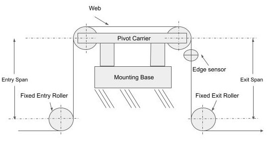
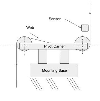
The reason it does not bend the web is that the web guide has an entry span, a span between the rollers on the pivot carrier or pivoting table, and an exit span, where the web is wrapped around all the rollers at a 90 degree angle. The table pivots around a point that is at the back edge of the entry roller on the carrier or pivot table. The two rollers on the table move in tandem, so there is no bending of the web in the region or span between the pivoting table rollers. In the entry and exit spans, the motion of the web with respect to the rollers is perpendicular, so the motion on the web is a twisting motion. This is the reason we call these the perfect web guide.
If the web guide is designed properly, it will have a one-to-one ratio; if you move the web guide one unit, the web will move one unit. Because there is no bending on the web, displacement web guides do not use the principle of normal entry for displacement of the web. The rollers on the table are parallel to each other, and the rollers that create the entry and exit span are perpendicular to the web, then there is no resulting bending of the web, and therefore, less stresses.
Installation
The 90o wrap
The proper installation of a displacement web guide requires a 90o degree wrap of the web around the rollers that create the entry and exit span and the rollers on the pivot table. However, a slight deviation of +/- 5o is acceptable.
Entry and exit spans
Regarding the length of the entry and exit spans, these should be at least 0.5 x the web width, with a recommended 1 to 2 web widths if it is possible. For stiffer webs such as metals longer spans, 3 x and above the web width, is recommended.
Sensor position
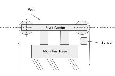
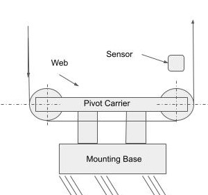
The sensor should be located as close as possible to the roller on the pivoting table in the exit span. This holds for all types of web guides, the sensor position is best when it is close to where the guiding action occurs. A general rule of thumb is to make sure the sensor is located within the first half of the exit span.
Guide span
The guide span is the distance between the centerline of the rollers on the pivoting table. This span is determined by how much correction is required. Typically, the pivoting tables will be allowed to pivot 5o to 10o. If you require greater correction you can design the pivoting table with a longer span. Guide spans can also be restricted on space available within the converting machine where the web guide will be installed.
You want to keep in mind that the plane of motion of the pivoting table is perpendicular to the entry and exit spans to guarantee a pure twist on the web at the entry and exit spans. As long as the rollers on the pivoting table are parallel to each other you will have the desired guiding effect.
The rollers on the guide span do not need to be on the same carriage or pivoting table. As long as they maintain the parallelism during the guiding motion, they will provide the web guiding required. You can even have a process occurring between the two rollers on the guide span, or even have multiple rollers within the guide span. In general, the guiding action occurs at the exit span.
Displacement guide no-no: What not to do.
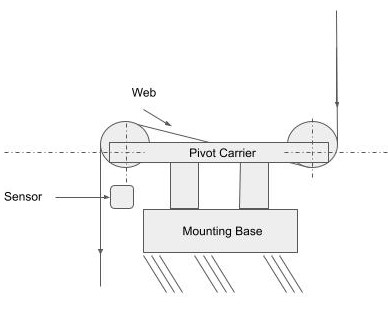
Sensor installed too far away or in the wrong span
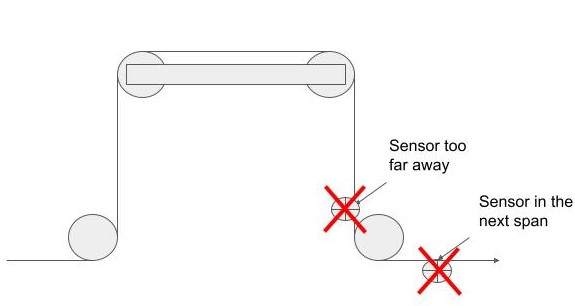
You don't want to install the sensor too far down the exit span, on the span following the exit span, or on any other span for that matter. In this case, when the web guide makes a corrective action that action will not be seen at the sensor immediately. In systems where the web is running at high speeds, you might get away with placing the sensor further down the exit span. However, on slower operations or when the web stops placing the sensor lower down the exit span or in the next span will lead to the web guide continuing its corrective action when it is not necessary. The result could be a damaged web.
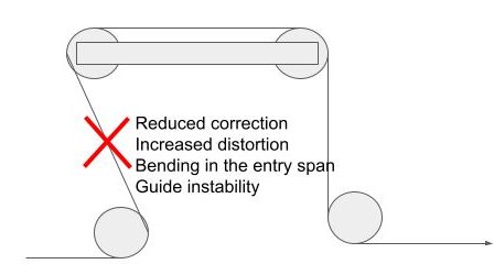
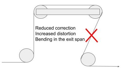
Wrap angle less than 90o
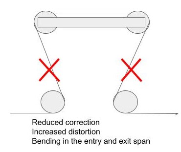
When the wrap angle at the entry span, exit span or both are below 90o beyond the +/- 5o tolerance you will introduce bending on the web with resulting understeering of the web. Additional effects would be increased distortion of the web, bending of the web in the span with the reduced wrap angle and guide instability.
Wrap angle greater than 90o
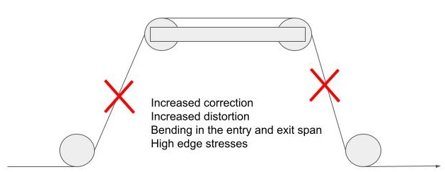
When the wrap angle is greater than 90o there will be over-steering of the web due to the bending effect on the web. As with the previous case, deviations from the 90o wrap around the entry or exit roller of the web guide will also increase distortions on the web and high edge stresses.
Displacement guide wrap options
Another design and installation issue with displacement web guides is the web path through the web guide rollers or guide wrap. There are four basic options that would allow us to orient the entry and exit path of the web through the guide:
Configuration A shows an inverted U-Path of the web on the web guide. This is probably the most commonly used web path in the converting industry
Configuration B presents a Z-Path for the web on the web guide system. The entry of the web into the web guide is from the top and exits down. This is an option where the web at the exit needs to remain in the same orientation as in the entry. It requires idler rollers on the entry and the exit to create the entry and exit spans.
 |  |
Configuration C is a similar Z-Path as in configuration B. However the direction of travel of the web has an entry from below and exit to an above span. Configuration D is an U-Path. This configuration is appropriate when the web guide is low on the converting machine and there is no room for idler rollers below the web guide to create the entry and exit spans.
Now, these four basic configurations lead to 16 different configurations just by placing the web guides in different orientations. Of importance is that the entry and exit spans are perpendicular to the guiding plane of the web guide.
Displacement Guide - Summary
Design considerations
The main displacement guide design consideration is the desired correction. As mentioned before, the desired correction will determine the guide span, the distance between the rollers on the guiding carrier.
Installation considerations
When dealing with installation considerations, space available, web stiffness, wrap angle at entry and exit and wrap options based on web path are the main considerations. Displacement web guides have the advantage that they can be placed close to the critical process in the converting line. However, the location of the web guide will be dictated by the amount of space available in the process. Web stiffness will affect the entry and exit spans. Stiffer webs will require longer entry and exit spans.
The location of the web guide must also consider the need to maintain the 90o wrap angle around the guide rollers for all the reasons mentioned before regarding the effects of an inadequate wrap angle. Finally, the wrap options for the path of the web through the web guide are determined by the web path through the converting machine.
Advantages of displacement guides
Displacement guides are very simple to install. Typically, the web guide mechanism will be supplied to the customer ready to install in the machine. Of course, this is highly dependent on how well your web guide supplier worked with you in the design and installation considerations early in the selection process. So, this point of providing the information of your web material, speed, tension, correction desired and space restrictions will payoff greatly when the web guide is installed and placed in operation.
Displacement web guides also place the least amount of stress on the web when dealing with intermediate web guides. However, in order to do this the web guide must be properly installed.
Best of all, these types of guides allow the designer and user a variety of installation options based on the different web paths that can be used.
Disadvantages
The maximum correction cannot be more than the guide displacement. More than a disadvantage it is a limitation.
So far, we have discussed two types of web guides, terminal web guides and displacement guides in the group of intermediate web guides. Our next blog will discuss the steering guide, another web guiding system in the intermediate web guide group. The best practice when selecting a web guide system is to discuss with your wbe guide supplier your needs and conditions. This will guarantee a proper selection of a web guide solution for your operation.
If you are interested in this and other topics related to web guiding and web monitoring, sign up for our monthly enews letter. There you will be informed of new solutions and applications and of webinars held throughout the year.
