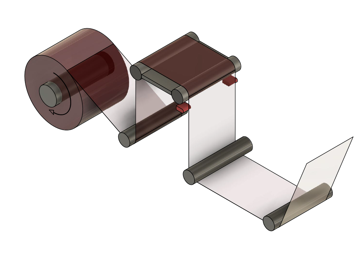
There are converting operations that require alignment of the web material to the centerline of the converting machine. In this case, you will usually find a two sensor setup for this type of guiding. This application is referred to as center guiding.
In our previous blog post we discussed the most basic of web guiding applications, one edge web guiding. In that case we were guiding to one of the edges of the web without regard to the other edge. (Read more on single edge guiding in our previous blog). The application uses a narrow sensing range sensor. It is the simplest solution for converting lines and it has its limitations and issues. In this post on center guiding, we will look at how center guiding works, its issues, and solutions with new technologies available.
Center Guiding
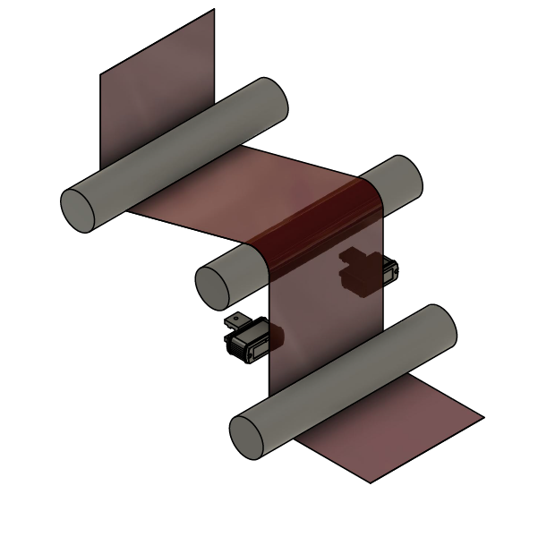
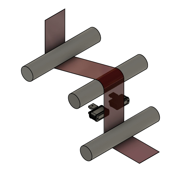
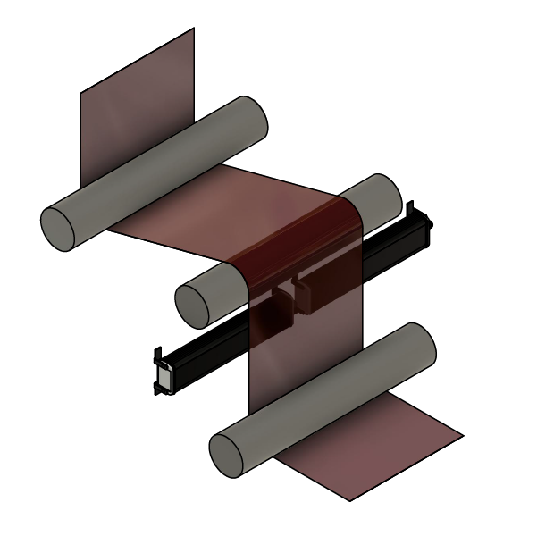
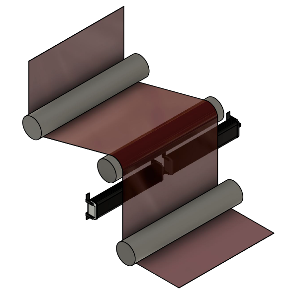
Center guiding is used when the converting process requires that the web is maintained in the centerline of the converting machine. The control system will take the value from two sensors and use the average of the values to provide the centerline position. The center of the web is positioned to the center of the distance between the two sensors.
Issues with Width Changes
When the converting line processes webs of different widths you need to reposition the sensors. This is due to the limited sensing range of the sensor. In this case the repositioning of the sensors is a little more complicated than the case of single edge guiding. Each sensor has to be moved half of the web width change from the center. Initially, this was done manually by operators or maintenance personnel by physically moving by hand the sensors from their position to a desired location. In operations where there are recurring widths, the operators mark the positions of the sensors for the different widths. In many cases these markings are made with rulers and markers, and are not very precise. As in the case of single edge sensing, the manual repositioning of web sensors introduces opportunities for operator error.
 |  |
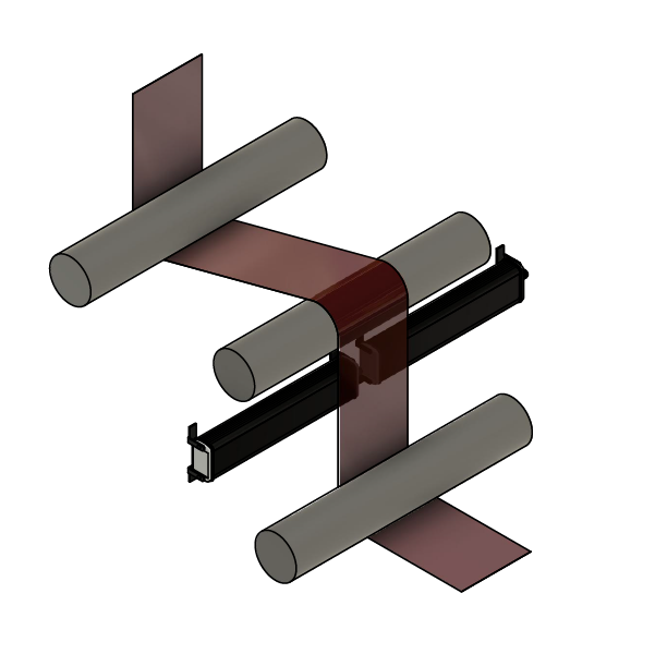
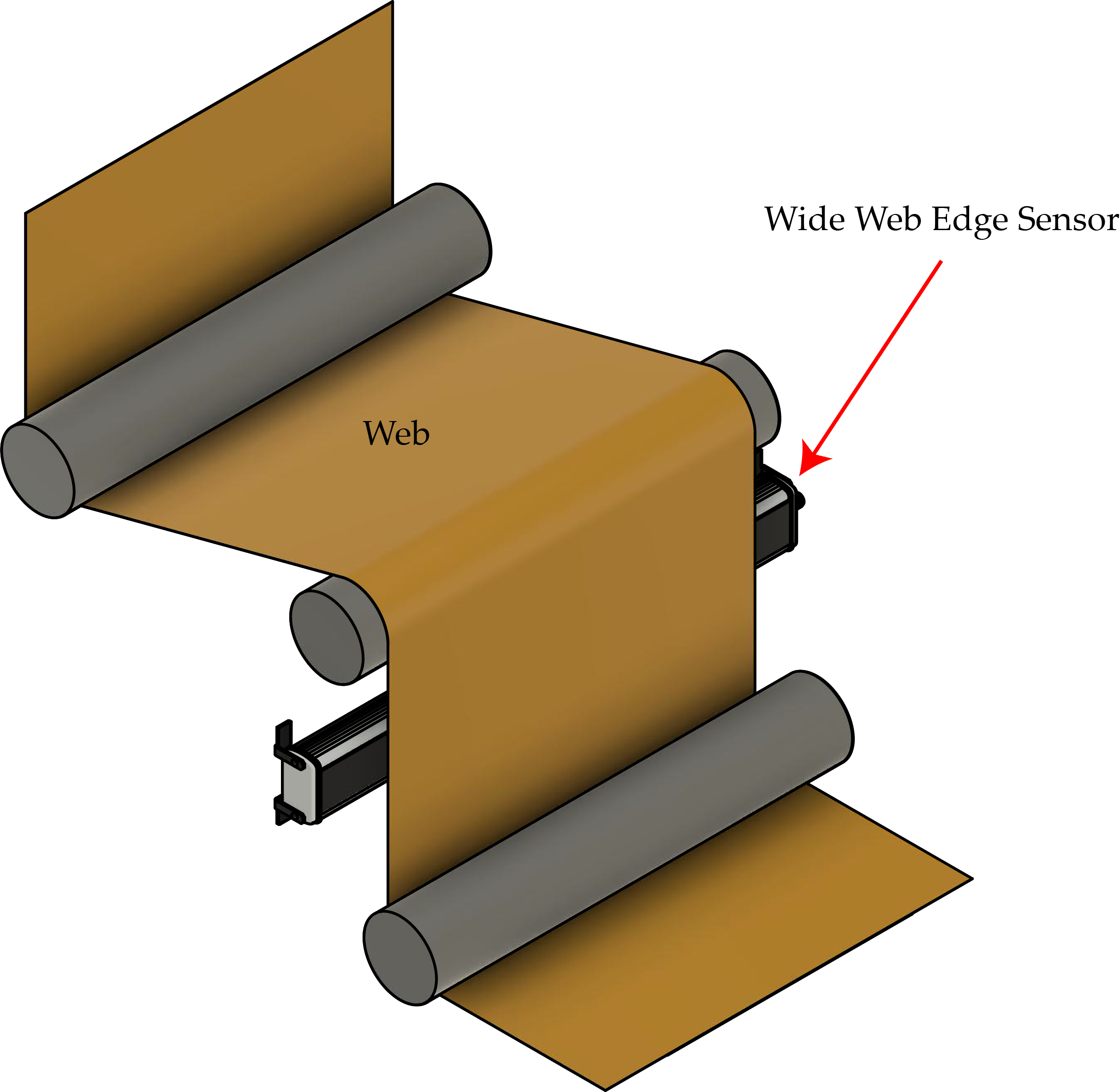
Sensor Positioners
One way to eliminate operator error from manual repositioning of sensors is to use an electromechanical sensor positioner. Electromechanical sensor positioners can be actuated manually or automatically through the controls. The two sensors would be mounted on a lead screw, with an actuator that would actuate the lead screw to move the sensors in opposite direction away from or toward each other. Additionally, it would require a control with operator interface to instruct the actuator to move the sensors. In the manual operation of the controls, the operator repositions the sensors, but has to visually certify the correct position of the sensor. This process is time consuming, requires the proximity of the operator to the location of the sensors in the converting machine, and is still prone to operator error.
An automatic sensor positioning system would consist of the two sensors mounted on a lead screw, an actuator that would actuate the lead screw to move the sensors in opposite directions from or toward each other, and a control. The operator can instruct the system to move the sensors to positions already predetermined. The automatic system would also be capable of continuously adjusting the position of the sensors as the sensor positioner chases the web. In this case, the complete guiding system would have two control loops based on the feedback from the sensors, one would provide the position of the web web for the purpose of guiding it and the other would provide the repositioning adjustment of the sensors.
Issues with Sensor Positioners
As any mechanical system, sensor positioners are subject to wear and tear. Their size occupies space that will restrict the location of the positioner on the converting machine. This location might not be the most efficient for guiding purposes. What’s more, the actuator is in constant motion to adjust the position of the sensors. Operation of the system is complicated, it has two control loops and two control gains that must be taken care of, one for the guiding mechanism and another for the chasing mechanism of the sensor positioner. This requires an additional drive aside from the guiding system. All this makes this type of system expensive and in many cases bulky.
Alternative Solutions
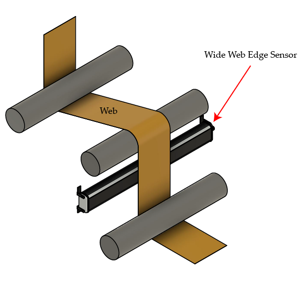
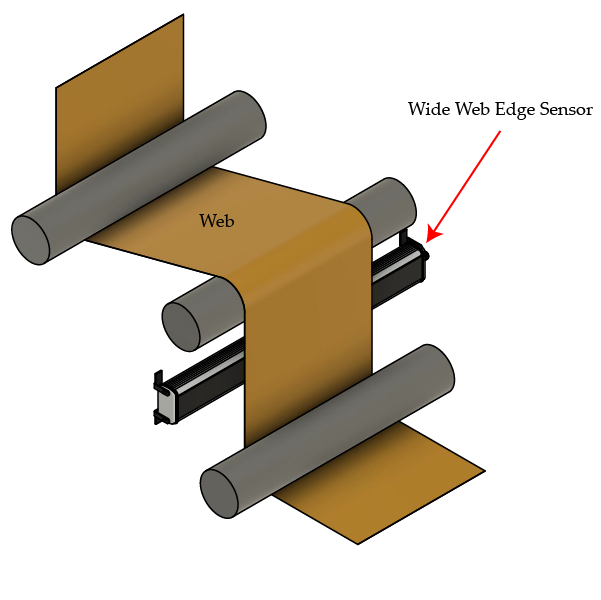
One recent solution that is becoming more popular is the use of sensors with wider sensing ranges. Converters can use two wider range sensors that can cover the web width change. In this case you eliminate mechanical moving parts, provide a simple installation and an overall lower cost of ownership.
For narrower webs there are sensors with a wide enough sensing range that a single sensor can cover the entire web. The development of camera based sensors with a single face allows for better placement of the sensors. In comparison, fork style sensors that might have wide sensing ranges still occupy a considerable amount of space. This restricts the locations where these sensors can be placed.
Like our technical and application blogs on web guiding and web monitoring? Sign up to receive our monthly newsletter. If you have a pressing issue in your converting line, make sure to tell us about it and we will do our best to helpThe use of wider range sensors and the most recent wide range camera based linear sensors are not limited to guiding. There are applications in web monitoring, such as width measurement. These will be discussed further in other blogs in the near future. Our next blog in this series regarding applications and advanced web guiding concepts will address guide points.
