Working Principle
The servo centering is a term used to indicate the middle or center position of a web guide mechanism. For an intermediate web guide this would be the position where the web guide mechanism would be aligned with the rest of the machine so that idle roller(s) on the web guide would be parallel to the other fixed idle rollers on the machine. With terminal guides this would usually correspond to the middle of the stroke of the unwind/rewind carriage.
Roll-2-Roll Technologies typically use a M12 24 VDC NPN inductive proximity sensor with a suitable target to detect the servo center position. The servo center position can be detected on the web guide structure, or on the actuator directly. It has to be noted that depending on the web guide structure and its installation, the middle of the actuator stroke might not always match with the center position of the web guide structure. However, the servo center position is the center position of the web guide structure and not the center position of the actuator.
The servo center sensor is installed such that it detects a target for one half stroke of the actuator and does not detect the other half of the stroke of the actuator. The transition zone will be the servo center location for the web guide mechanism. The figure below shows the working principle of the servo center sensor at different positions of the target.
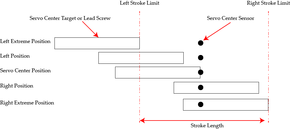
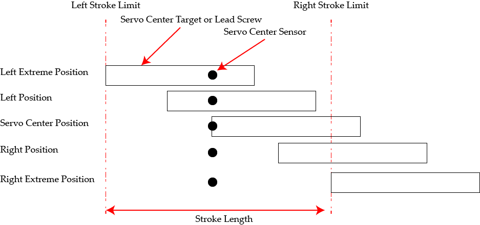
When the servo center button is pressed on the web guide controller, the initial state of the sensor is recorded before moving the actuator in a direction such that the transition or home position is reached. The direction in which the actuator/target/lead screw moves depends on the polarity setting of the servo center functionality. If the target position is reversed then the different scenarios for the servo centering operation would also have the opposite polarity as shown in the following illustration.
When the servo centering operation is started, the actuator would move in a direction to see the transition point. Since a proximity switch the change of state could have a hysteresis depending on the direction of motion of the actuator. To ensure that the transition is always at the same location, the servo center operation could continue to move the actuator past the transition point and then bring it back. This functionality is implemented in some versions of the web guide controller.
Note that if the servo center polarity is set incorrectly, the actuator would move away from the center position. Additionally, if the distance between the target and the proximity sensor goes beyond the working distance of the proximity sensor the functionality of the servo center operation would be affected. Standard working distance for inductive proximity sensors are around 1.5 mm to 3 mm.
Pre-installed Servo Center Sensor on Web Guide
For most web guides made by Roll-2-Roll Technologies, the servo center sensor would be pre-installed at the appropriate location with an appropriate target. For some models of the web guide mechanism, the proximity sensor might look at the lead screw on the back of the actuator. This would be the standard polarity for the servo center operation as shown in the first illustration. For some other models, the servo center sensor would look at the linear slide carriage connected to the rod end of the actuator. This would correspond to the reversed polarity of the servo center operation as shown in the second illustration.
No adjustment is needed when the servo center is pre-installed on the web guide mechanism.
Servo Center Sensor on Upgrade and Retrofit Actuator
The Roll-2-Roll actuators that are used in upgrade and retrofit applications may have the servo center sensor installed on the actuator with an appropriate mounting bracket. The proximity sensor would be installed to look at a translating linear support shaft of the actuator. If the sensor is not installed on the actuator, then the user can install the sensor looking at the exposed lead screw of the actuator (as shown below) or with a dedicated target.
A provision to linearly move the proximity sensor parallel to the stroke of the actuator allows the user to set the transition point anywhere on the stroke of the actuator. This enables the proper location of the transition point based on the center position of the web guide mechanism, rather than the center of the actuator stroke.
Most often the available mechanical stroke length on the actuator may be more than the stroke available on the web guide mechanism. Once the servo center sensor is installed at the middle of stroke of the web guide mechanism, the electronic stroke of the actuator can be adjusted so that the actuator never hits the mechanical limits of the web guide mechanism. This increases the life of the actuator and avoids any premature actuator failure.
Servo Center Sensor on Unwind/Rewind Carriage
Depending on the actuator used, the servo center sensor can be installed on the actuator or installed to look at a target that moves with the unwind/rewind carriage. If the lead screw on the actuator is exposed then the servo center sensor can be installed to look at the lead screw.
Importance of Servo Center
Servo centering a web guide is an important step for good web guiding performance. This is because when the web guide is servo centered before a production run, the web guide would have equal stroke on either direction to correct for any errors. If this step is skipped, it is possible that the web guide mechanism might have a bias towards one side before the start of a new run. This bias could limit the correction in that direction if the actuator stroke limit is reached in that direction during the run.
Roll-2-Roll web guide controllers use the servo center position as the zero position of the actuator which is used for the electronic stroke limit. The actuator would only move one half of the electronic stroke limit on either side of the zero position. If this sensor does not work or if the zero position is incorrect, then the web guide performance may be limited because of the electronic stroke limit.
Document Text
Show document text (1093 words)
Servo Center Sensor Installation 1110 S Innovation Way Dr Stillwater, OK 74074 E: sales@r2r.tech W: https://r2r.tech P/F: +1-888-290-3215
Working Principle
The servo centering is a term used to indicate the middle or center position of a web guide mechanism. For an intermediate web guide this would be the position where the web guide mechanism would be aligned with the rest of the machine so that idle roller(s) on the web guide would be parallel to the other fixed idle rollers on the machine. With terminal guides this would usually correspond to the middle of the stroke of the unwind/rewind carriage.
Roll-2-Roll Technologies typically use a M12 24 VDC NPN inductive proximity sensor with a suitable target to detect the servo center position. The servo center position can be detected on the web guide structure, or on the actuator directly. It has to be noted that depending on the web guide structure and its installation, the middle of the actuator stroke might not always match with the center position of the web guide structure. However, the servo center position is the center position of the web guide structure and not the center position of the actuator.
The servo center sensor is installed such that it detects a target for one half stroke of the actuator and does not detect the other half of the stroke of the actuator. The transition zone will be the servo center location for the web guide mechanism. The figure below shows the working principle of the servo center sensor at different positions of the target.
When the servo center button is pressed on the web guide controller, the initial state of the sensor is recorded before moving the actuator in a direction such that the transition or home position is reached. The direction in which the actuator/target/lead screw moves depends on the polarity setting of the servo center functionality. If the target position is reversed then the different scenarios for the servo centering operation would also have the opposite polarity as shown in the following illustration.
When the servo centering operation is started, the actuator would move in a direction to see the transition point. Since a proximity switch the change of state could have a hysteresis depending on the direction of motion of the actuator. To ensure that the transition is always at the same location, the servo center operation could continue to move the actuator past the transition point and then bring it back. This functionality is implemented in some versions of the web guide controller.
Note that if the servo center polarity is set incorrectly, the actuator would move away from the center position. Additionally, if the distance between the target and the proximity sensor goes beyond the working distance of the proximity sensor the functionality of the servo center operation would be affected. Standard working distance for inductive proximity sensors are around 1.5 mm to 3 mm.
All Rights Reserved. Copyright © 2019 Roll-2-Roll Technologies LLC Page 1 of 3
Pre-installed Servo Center Sensor on Web Guide
For most web guides made by Roll-2-Roll Technologies, the servo center sensor would be pre-installed at the appropriate location with an appropriate target. For some models of the web guide mechanism, the proximity sensor might look at the lead screw on the back of the actuator. This would be the standard polarity for the servo center operation as shown in the first illustration. For some other models, the servo center sensor would look at the linear slide carriage connected to the rod end of the actuator. This would correspond to the reversed polarity of the servo center operation as shown in the second illustration.
No adjustment is needed when the servo center is pre-installed on the web guide mechanism.
Servo Center Sensor on Upgrade and Retrofit Actuator
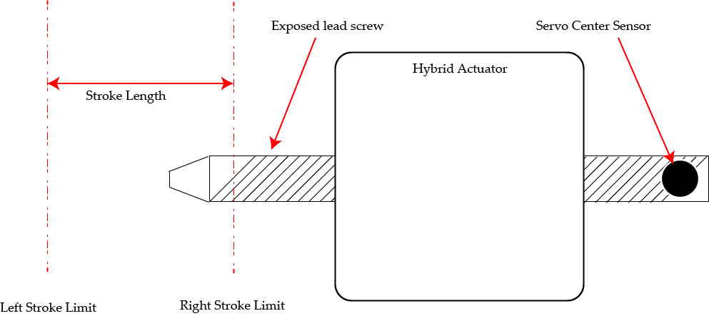
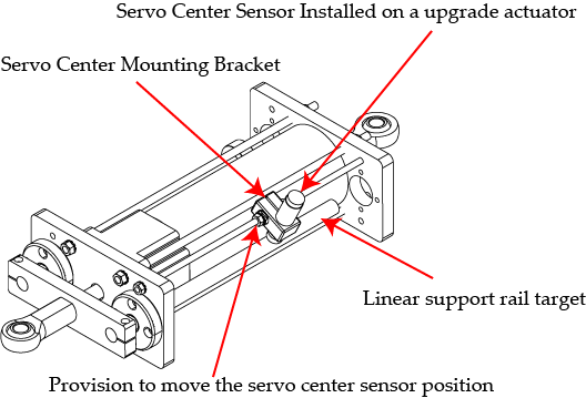
The Roll-2-Roll actuators that are used in upgrade and retrofit applications may have the servo center sensor installed on the actuator with an appropriate mounting bracket. The proximity sensor would be installed to look at a translating linear support shaft of the actuator. If the sensor is not installed on the actuator, then the user can install the sensor looking at the exposed lead screw of the actuator (as shown below) or with a dedicated target.
A provision to linearly move the proximity sensor parallel to the stroke of the actuator allows the user to set the transition point anywhere on the stroke of the actuator. This enables the proper location of the transition point based on the center position of the web guide mechanism, rather than the center of the actuator stroke.
All Rights Reserved. Copyright © 2019 Roll-2-Roll Technologies LLC Page 2 of 3
Most often the available mechanical stroke length on the actuator may be more than the stroke available on the web guide mechanism. Once the servo center sensor is installed at the middle of stroke of the web guide mechanism, the electronic stroke of the actuator can be adjusted so that the actuator never hits the mechanical limits of the web guide mechanism. This increases the life of the actuator and avoids any premature actuator failure.
Servo Center Sensor on Unwind/Rewind Carriage
Depending on the actuator used, the servo center sensor can be installed on the actuator or installed to look at a target that moves with the unwind/rewind carriage. If the lead screw on the actuator is exposed then the servo center sensor can be installed to look at the leadscrew.
Importance of Servo Center
Servo centering a web guide is an important step for good web guiding performance. This is because when the web guide is servo centered before a production run, the web guide would have equal stroke on either direction to correct for any errors. If this step is skipped, it is possible that the web guide mechanism might have a bias towards one side before the start of a new run. This bias could limit the correction in that direction if the actuator stroke limit is reached in that direction during the run.
Roll-2-Roll web guide controllers use the servo center position as the zero position of the actuator which is used for the electronic stroke limit. The actuator would only move one half of the electronic stroke limit on either side of the zero position. If this sensor does not work or if the zero position is incorrect, then the web guide performance may be limited because of the electronic stroke limit.
All Rights Reserved. Copyright © 2019 Roll-2-Roll Technologies LLC Page 3 of 3