For a complete overview of web width measurement with Roll-2-Roll® Sensors and Roll-2-Roll® Controller please visit this page: https://r2r.tech/articles/web-width-measurement-and-monitoring-applications-and-technology
For more information about the SCU controller please visit: https://r2r.tech/products/roll-2-roll-controller
Transcript
Show full transcript (1174 words)
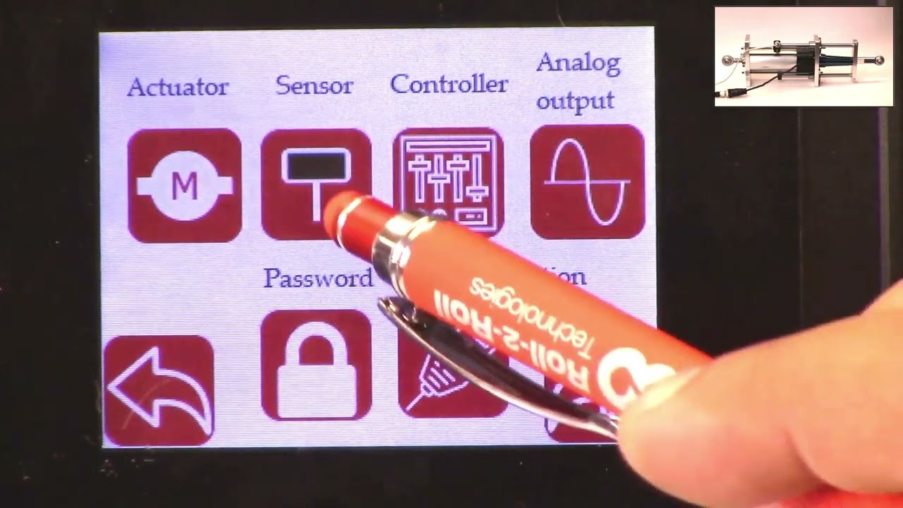
in this video we're going to look at how we can set up the controller scu5 controller for width measurement with two sensors I've got a couple of sensors installed here one is 112 both of them are 112 sensors one of them is looking at the left edge of the web and the other one is looking at the right edge of the web when we are doing width measurement with two sensors what we would ideally like to have is two sensors of the same range that means that if we have a 112 here we would also like to have the 112 there and then we also want to have the two sensors with the same orientation in this case this particular sensor has the connector coming on the right hand side this is behind the web it's on the right hand side and likewise for this connector it's coming on the right hand side and that's what we need because our camera has the pixel one here and then the nth pixel here and then for here the pixel one is here and we have the nth pixel there if we have one cable coming out this way and the second cable coming out this way this camera has to be inverted which is not ideal and it will not give you the correct output now if both cameras are inverted that's fine we cannot have one camera straight and the other camera inverted and that's an important thing that we need to keep in mind when we are using two sensors so we have those two sensors one is looking at left and the other one is looking at right we're gonna go into the controller and show how we can set that up so go into the tools icon power user sensor in this case we had sensor 1 disabled so we're going to enable that and we also have the sensor one looking at the left edge of the web so we're going to set that to left Edge and we're going to set that to right Edge for Sensor 2 and then again we're going to go into the operator screen go into the sensor a Sensor 2 image is pretty solid switch over to Sensor One the sensor one image is also solid but the only thing that we want to do is we want to make sure that this automatic brightness is set to freeze and then increase that brightness just a little bit so that we have that the web position is pretty close to the edge of the sensor that's fine if you need to move it you can move it so I'll just go ahead and move that sensor back in so that we have it within the range and there we go now we can go back to sensor two both sensors have the range set properly and then next we need to make sure that the output mode is an analog analog output mode is in width again we'll go back to 10 volts for now just for measurement purposes and then that's done and the final thing that we need to do is to actually set up the um the teach the controller for the width measurement so if we go back to the setup we can see that we have two sensors and the sensors are certain distance away from each other we actually don't know what the distance between them are and the easiest way for us to set that distance is to actually teach the sensors for that distance and again for all width measurement applications we want to make sure that the web is stable and we don't have any plane change so it's supported between two rollers here so it's pretty stable and we want to make sure that we don't change that while we are running in the sense of the plane change now in order to teach the sensor what we are going to do is we're going to actually measure the width of the web so it's about eight inches wide and go into the controller here and go into the tools icon operator width and just to make it easy I'm going to go to the units inches and go to width and then eight inches is the nominal width I'm going to set that to 8 inches and then I'm going to keep the output type as absolute and now I need to go in and press the teach button and then give it a few seconds and then accept what this teaching procedure is doing is that it's taking the nominal width entered in this controller and it takes the measurement from each sensor and then it computes the distance between the two sensors that's the way in which we're able to teach the controller for the distance between the two sensors as long as the the distance between the sensors are not changing as long as we are not moving these sensors if the width changed you don't have ever have to teach it again because the teaching procedure is only setting up the distance between the sensors and and there's no need for us to teach every time the width changes this is a one-time procedure and as long as all the settings are the same then we don't have to re-teach the just like the single sensor mode if you go in to the controller we can set the output type as absolute or header so if you set it as absolute the display value is going to provide an absolute measurement and if the width increased or decreased it's going to show that value so if I put in an extra one you can see that the value increased or decreased based on that now you can also set that up to oops set that up to error and in this case it's going to provide an error output so if I add something you can see that the error changed increased and that's essentially it so few things to keep in mind when we are looking at the width measurement with two sensors so we have the sensor position indicators here so we we got the sensor one as the left sensor here and Sensor 2 as the right sensor those are indicated and we have a split screen here the left side is showing the left sensor or sensor one and the right side is showing the right Edge or the Sensor 2 the green line here is showing the center line position of the web with respect to the two sensors and then the label here shows the width and then right now is showing the error and if we want to set it to Absolute and it shows the absolute value there that's how we set up the width measurement application for two sensors and in the following we'll also look at the analog output when we have two sensors

How to setup Web Width Measurement with SCU5 Controller using a Single Sensor
Transcript
Show full transcript (1542 words)
hello everyone today we're going to look at we're going to look at how do you measure width of the web with just one sensor we have some videos in our website about this but in this video we're going to look at a few different things one is the teaching procedure there is a small teaching procedure that we need to do whenever we are doing a width measurement and then we're also going to look at different output options that we have from what we have is a sensor that is connected to our seo5 controller and and the controller showing the width of the web and we'll go over how we set these up and also get the output from the controller first and foremost depending upon the application in this case we are looking at width of a web with one sensor so we need to make sure that we have those set properly go into the tools the power user sensor Sensor 2 is the one that we are looking at and now one is set to Center mode if we use One sensor and we need to look at both edges of the web Center mode is the way to in the following videos we'll talk about two sensors and how do we use two sensors for width measurement but with one sensor we need to have the sensor set up in sensor mode Center mode and then we go in and make sure the image is looking good this screen just provides us a real-time preview of what the sensor sees and it allows us to set some of the parameters for the image capture one of the key things for width measurement is that the web needs to be stable so in this case web is supported between two rollers so that the plane of the web doesn't change and we want to make sure that the plane of the web doesn't change because this is essentially a camera when the web moves farther or closer like what I'm showing right now it will change the width measurement just because of the fact that the image is going closer or farther away or the image is in Focus or it loses focus and that is not ideal for us and as you can see if I have the web move farther and closer you can see that the image is changing we don't want that image to change ideally we want to have a solid image like that this is a good image and this is not an Ideal Image anytime we do width measurement we need to make sure that the plane of the web is stable the best way to do that is to install the sensor between two fixed rollers that's what we have in the setup here and then that way we can take care of that that's the first thing for the width measurement application is that we don't want to measure the width of the at the exit of the web guide because at the exit of a web guide the corrective action of the web guide is going to change the plane of the web and we can measure the width but that's not going to be accurate to 5 000 of an inch like what our sensor can do that's the first and foremost thing that we want to do and if we go into the controller and the main thing that we want to set in this screen for which the measurement is set the brightness so that we have a pretty solid image make sure that the plane of the web is stable and we also want to make sure that the brightness is Frozen for width measurement and the main reason for that is when you set it in automatic brightness I'll just show you it kind of picks up sting features the algorithm that is used to do that is not only looking for a certain image but also looking for certain things within the image that's not ideal for us ideally the easiest way for us to do it is thread the web have some tension put it in automatic brightness freeze the brightness and increase the brightness just a little bit so that you don't see that any more lines in between so you want to see a solid image like that and that's what we want to do once we have this set up like this now we can go into the analog output mode to make sure that the analog output is in width measurement and we can go in once that is done we have the web stabilized we have the brightness set to a certain value we have made sure that the analog mode is in width now we are ready to teach and that can be done in the operator menu so we go into operator and go into the width so the main reason why we need to teach the controller for the right width is because we might have set the plane of the web at any arbitrary location we might have changed the brightness to any arbitrary brightness all of these effects the the accuracy of the width measurement and anytime we change any of those settings we do need to teach the controller for the width and that way we are fixing all the parameters and making sure that the measurement that we are getting is the right measurement in this case I'm going to go in to teach the sensor or the controller for the right measurement ideally ideally we want to measure the width of the material and whatever that value is we're going to put it into the nominal width in my case right now I think this is about 65 millimeters so I'm going to set it to 65 millimeters right there and approximately 65 millimeters and we're ready to teach when we are all that we need to do to teach the controller is that we're going to press this one button and give it a few seconds and then press accept what it does is that the controller is going to take that picture computer width of the web it sees and however long you're waiting it's going to take an average of those measurements and then once that is done and when once you press accept it's going to compare those average and what the nominal width is and it's going to create an offset or basically a calibration and that's how we know what the right width is and from now on that's going to be the width output as long as the settings don't change this is a one time basically one-time procedure you don't have to come back here and do it every single time that's about it so now the sensor is calibrated for the required width and if we have the web width change a little bit you can see that effect there on the controller output so if you have the width change let's say I introduce something here and you can see that the measurement is providing the output it is providing so that's as simple as it is to set up the system for width measurement with a single sensor like I said the thing for width measurement is that we need to have the web State the web can be at a certain distance anywhere from quarter inch to maybe half an inch but while the machine is running we don't want that distance to change at all and that's because of the focus thing that I mentioned one other thing right now all the units are in millimeters if you want to change the units on these you can go into the tools icon operator display and then change that to inches so you should be now able to see the values in inches and then when you teach the web again all of these values are again in inches that's for teaching the system for One sensor one other thing that we can look at is the output that is displayed here that's the width of the web there are some applications in which we don't really care about the width of the web we want to see how much is the web width different from its nominal width and that's pretty easy for us to do all we need to do is go into the tools icon and then press the operator width and then the output type instead of saying absolute we're going to make it as error and now if you go back to the home screen this is displaying the error in the measurement this is basically 15 thousands of an inch and again if you want to look at that in millimeters that's about 0.381 millimeters so you can either look at the actual width or you can look at the absolute width with this system anyway please subscribe to our Channel and take a look at other videos that we have on how to use our products and how it can benefit your application thanks
This video shows how to import SCU5 controller as a device into EtherCAT with the ECS file.
👉🏻 EtherCAT ECS File for SCU5 firmware Version 3.5+ using Hilscher Module:
🔗https://r2r.tech/documentation/ethercat-ecs-file-scu5-firmware-version-35-using-hilscher-module
Transcript
Show full transcript (510 words)
hi this is Carlo from Roll to roll Technologies and in this video I'm gonna show you how to add a su-5 controller into a backoff automation system with green cards here is my setup I have my industrial PC over here where I set the one of the parts to be either cut master and I connected this industrial PC directly to my su-5 over here and I can see into the settings in the communication setting I have a either cut version of the su-5 and because it's a either system I don't have IP address of setup mask or Gateway I will only have the Mac address over here first step we were gonna head to our website r2r.tech and download the ESI file for the su5 I'm gonna go into resources documentation and then support file and I'm gonna look for the ethercat file I'm gonna do right click and save link as and I'm gonna choose the directory when I want to save my file and do save and gonna go file was saved now I have to copy this file into the proper directory so I'm gonna copy this and go PC twin cut 3.1 this is my version configuration config IO either cut and I will pass that in this directory then I'm gonna go and Open my cut software and I will go into twin cut ER cut devices and do reload device description at this point there are two ways to add the SEO 5 to your io3 one way is to go over here in your either Cuts Master right click and do scan with scan for new devices and here I have the roll to roll device by doing this procedure you will have all the register a very descriptive name but just with the register number we this is a way to do it but we will suggest to add it by using the ESI file that we just downloaded so you will go here into your ethercat master and add a new item search for the role to roll technology category and add the su-5 by doing so you will have variable there are much more descriptive but for the input and for the output and now once we have done this if you do go back to the internet eater Cuts master and do the scan it will recognize the device and if you toggle this button to show online data you can go in and verify that the connection is present for example if I look at the left edge of the sensor and do the online data when I pass something in front of the sensor the listening become bit I see the data updating the show me that I have a good connection to the SEO 5 and then you can link the variable to your program and you're good to go and this was all I have for today's video if you are interested to our video subscribe Below have a good day
This video shows how to import SCU5 controller as a device into PROFINET ecosystem with GSDML file.
The different versions of the GDSML files based on the ethernet module are available on our website here:
👉🏻 PROFINET GSDML File for SCU5 firmware Version 3.5+ using Hilscher Module: 🔗https://r2r.tech/documentation/profinet-gsdml-file-scu5-firmware-version-35-using-hilscher-module
Transcript
Show full transcript (1062 words)
hello everyone in this video we're going to look at how we can configure our sg5 controller with the profinet industrial Internet Protocol on it with a profinet controller we don't have a profinet controller here but we're going to use a profinet Master stimulator to show how we can add our scu5 controller to a profinet controller using the HTML file I have a controller here and this is with a profinet industrial Internet Protocol the way we can check what industrial ethernet protocol we have is to go into tools and then hit the power user communication and then other shows that we have a profinet device and then we also support a couple of different vendors for these industrial ethernet protocols one is hillshare and then the other one is HMS essentially the configuration for either of them are exactly the same except that for hillshare you need the right heel share files and then for HMS you need the right HMS files support files the gdsml file now that we know what module we have we can go to our website and see how we can get that information so if you go to our website r2r.tech and then go to resources and documentation within this menu we're going to click on the support files and it shows up a variety of support files that we have today we're going to look at how to add the profinet so we're going to look at the profinet esdml file like I said we have two different modules one is hillshare and the other one is HMS the the steps are exactly the same but we just need to make sure to download The Right files so in this case it's hillshare I'm going to right click on that and then say save linkcast and then put it in a location where you can pick it up so that's I'm going to save it once this is done then in our case we're going to show how we can do it with a master simulator but in your specific application you're going to use that specific controller software maybe Tia portal or S7 whatever the programming language for S7 is for the Siemens you're going to use that to import it so we'll show how we will do it with the um Master simulator okay we're going to open Master Simulator the profinet master simulator if you have multiple network cards you might have to choose the network card that you have but in our case we don't have multiple network cards so we're just going to select that and then we can start looking for the device once you open that it's going to automatically pull up that interface search the network for the profinet device just to confirm that this is our device you see the MAC address of the device and if you go back to our controller and you can see the MAC address and it ends in 83 and that's exactly what we see on the computer as well we can give whatever name we want for this so we're going to give a name and then with the profinet the network actually sets the IP address for the controller so what we're going to do is we're going to go ahead and set that so in our case we're going to set the IP address for our controller from this program so I'm going to set it as 192. 168 one I'm going to give maybe 103 as the IP address subnet is 255 255 255 0. and then the Gateway is 192 168 1.1 and then I'm going to apply that and it will update that IP address and all the network information so once we do that then we have set the IP address of the controller from the from this profinet master and we're good to go obviously right now you can see that it's not connected that's because we want to make sure that we're able to configure that in order to configure that device you do need that gsdml file and I'm going to go in and open that file from the location that I downloaded and the main thing for this when we import the GDs ddsml file is that we actually need to set a few things and one of the first things is that the actual device that is connected and that is available in dim 17 nic-52re this is what we want to look for so we're going to select that device access point as dim 17. and then we need to set the input and the output from from our controller properly so we have 32 input bytes so we're going to select 32 input bytes and the input can be put any of these slots either 5 or 8 so I'm going to select five and set that input 32 bytes to slot 5.
and then the output is actually 16 bytes and so I'm going to select 16 bytes as the output and then the output can be selected in slot 1 or Slot 4 so I'm going to select it to slot 4. and that's about it and then I can apply now once this is done I can click on the start and now it's going to bring up the device and basically we can see the i o data input is actually the output from our su5 controller and then the output that you see here is actually the input to the scu5 controller and you can see that the connection state is there it's established it says the MAC address on our device also if we have some some data coming in you can see that on both on the controller and the device if I have some my finger in front of the sensor you can see that the data is updating so that's essentially the way in which we can import the scu5 controller into the profinet ecosystem using the gdsml file the steps are exactly the same for for either the HMS or the Hillshire only that we need to get the right gdsml gsdml file for that but anyway that concludes our demo on how to import the scu5 controller with the profinet industrial ethernet protocol into a Siemens ecosystem and please subscribe to our channel for more informational videos and we'll see you soon

This video shows how to import the SCU5 add-on instructions in Rockwell Automation Studio 5000. With the add-on instructions the use can easily parse the data from the SCU5 controller and can readily get up and running with the SCU5 controller.
The different versions of the add-on instructions are available on our website here:
Transcript
Show full transcript (1297 words)
hi this is Carlo from Roseboro technology and today I'm going to show you how to import our add-on instruction to be used with our su5 controller first of all let me show you my setup I have my Rockwell PLC over here I have an su-5 controller over here and I have a sensor over here that we will use for testing and here on my studio 5000 I have already added my su5 controller over here and you can watch our video on how to do that and now I'm gonna import our add-on instruction to be used with the su5 controller I'm gonna head to our website rolltrol.text slash documentation and I have selected support file over here and I'm gonna look for the Rockwell Automation add-on instruction I'm gonna do right click save links as choose the folder where I want to save my add-on instruction save then heading back to Studio 5000 we're gonna go on add-on instruction right click import that on instruction go back to the folder where I downloaded the add-on instruction select the add-on instruction click this if you want to change the name you can change the name here otherwise I'm gonna go ahead and say okay and now I have the add-on instruction added over here and then all the user defined variables are over here then I'm gonna go over and to my program or wherever I want to add the add-on instruction look for the add-on extraction over here and SEO five add-on instruction click the add-on instruction gets dropped there now I have to Define the variables for my add-on instruction I'm gonna call it su5 then I need here I'm gonna have to link the input and output variable for the add-on instruction to the input and output variable of my controller in this example our controller is called demo and this is the variable I need to link and then the output variable into demo this one and this variable the name of this variable will change depending on the name that if you go into the io3 the name of the SEO file controller that you want to link the aoi tool needs to match this input and output variable over here and now I'm gonna create the variable for the output of the aoi I will call this demo to sensor one and the from variable are variable there are reading data from the sensor while the two variables are that are used to control the sensor and I'll do the same for sensor 2. demo from to name two minimum this variable is used to control the brightness of the sensor and for the web guide the same concept the from variable are data coming from the web into the plc and two variable are demanded actually control the webcam okay now I need to add all of this variable so I'm gonna do right click Nemo I will leave all of these to the default value create I repeat that for all the variable create here I have named all the variable if you still get an error over here most likely you have forgotten to create one of the variables in this case I did that on purpose I forgot to create this one and now once everything is in order you will have no error and you also if you look at project variable you will have all the variable from that you have created over here and each of these variables have meaningful feel that you can use to either read data from the sensor like if the sensor is present low contrast in a web and all of these or the the sensor position The Edge position and all the data coming from the sensor okay now I'm gonna download this project and try to see the data coming from the sensor and make sure that everything went well in my aoi so I'm gonna go over here go online and I Do download I'm online I'm in run mode everything is okay the i o is okay which shows that there is a good connection to the su5 controller now I can verify that the data is coming through properly and I can already see that sensor 1 shows no sensor zero which means I have a sensor connected I don't have it in front of the sensor so it shows me low contrast and the web now I'm gonna put my pen in front of the sensor and I can see the data changing and I have the position of the pen over here changing so everything is working and this is the data coming from the sensor now if we want to control the sensor we will go to the two and one thing that it's important to know that this through this variable you can enable and disable the sensor so right now we have a sensor that is enabled in the controller and you can see from the green box over here in the controller but if I put a zero in this field over here and press enter this will disable the sensor so if I go back to this controller now you see the sensor has been disabled one thing to notice is you don't want to this to zero you is better you have to choose a value put it as of known and the values that you can choose are if you go over here and over here it shows you all the possible value that you can choose for this just remember not to leave it as zero otherwise the sensor will be disabled now you can also control the orientation of the sensor to do that you have to set this field as a one and now if this is a zero I can go in my SEO file controller and see this is a left controller if I change that field to two is going to switch to a right controller over here and if I switch this to three is going to be in Center mode here on the controller and if you go over here and over on top of the description it will show you all the options that you have for that value now common mistake that we have seen one is to name this variable for sensor 1 and Sensor 2 with the same name this will cause the aoi to overwrite the value and you will only see the the values from Sensor 2 most likely and other things is no matching the version of the aoi with the version of the controller so the version of the aoi will be shown either here or in the aoi menu over here and you have to make sure when you go into the controller you have the version of the controller over here you want to have a version of the aoi that is the closest to the version of the controller that you have and always a version of the aoi that is below the version of the controller one other problem that we have seen is that if you say you have installed their older aoi and you want to upgrade to a newer aoi it's always best to delete the older aoi and delete all the user defined variable and install new aoi from scratch rather than trying to upgrade a newer aoi the older one already installed on the system and these covers all that I have for today thanks for watching and if you want to stay up to date with all of our videos please subscribe to our Channel down below and have a good day
How to set the servo center position or the home position using the SCU5 controller.
- 1: 22 Physically installating a proximity sensor to detect the home position.
- 4:32 Changing the polarity of the servo center sensor.
- 5:39 Some common problems with servo center or proximity sensor installation.
- 7:00 Servo center position based on the electronic actuator position.
- 8:30 Setting the servo center position electronically.
Transcript
Show full transcript (2140 words)
hello everyone today in this video we're going to discuss how we can use our upgrade kit actuator and specifically how do we set the servo Center position Servo Center is basically a term that an industry term that is intended to mean the center of the servo or the hydraulic cylinder but over times it it has changed but essentially what it means is that if you have a web guide mechanism and you want to thread up the web on the mechanism and is there a quick way for us to set the actuator to a position that would make sure that the web guide is parallel to all the other rollers in the machine and historically it's been called the servo Center position you can also call that a home position or whatever you want to call it but the ideal thing is that if the web guide let's say you stop the machine the web guide is to one position and you want to quickly bring that web guide to a home position or a center position and that's what is called as a Servo centering in our system or in our upgrade kits we do provide a couple of ways in which we can achieve that functionality one of the things one of the ways in which we achieve that is by actually physically installing a sensor we call it a Servo Center sensor to detect the home position in this actuator that we have um you can see that there is a sensor that is installed this is basically an inducto proximity sensor it's trying to look for this Race Rod when this Race Rod moves back and forth you can see that the servo Center there's a light on that switch there's a light right here and that light will actually go off or on in this upgrade kit actuator the servo Center functionality is enabled by using the serval Center sensor all that the sensor is doing is trying to locate this Race Rod and the transition from seeing the racer rod and not seeing the Race Rod is basically the home position so just to illustrate that I'm going to move this actuator and you can see that there is a LED kind of thing that lights up and if I move it out and that turns off and that is essentially the servo Center position when you install this upgrade kit on your web guide mechanism what you can do is you can actually Center the web guide manually by jogging left hand so you can jog it left and right wherever you want it to and then the position where the frame is parallel to the rest of the rollers in your machine once you've figured that out then you can actually move this mechanically move it to the location where you think that Servo Center where that transition is going to happen and that that would be the easiest way to set the server sensor okay so just to show that the servo Center functionality we're going to show what happens when we hit the servo center button on the scu5 controller so if I go back to my controller and let's say I have jogged the web guide now you can also see the actuator position on the top right and if I hit the servo center button it's going to go until it sees that proximity switch and the light turns on so if I'm coming from the direction where it doesn't the light is off it's going to go until the light turns back on and if I do the opposite let's say I go in this position where the light is on and then I hit the servo center button it's going to go until the light turns off and then it's going to start turns off and then it's going to stop there so that's how you install the servo Center on our actuator in terms of how what the location is based on the centering there are some situations where you might not have the ability to install the sensor we do have a we do provide an additional option where we can change the polarity of the servo Center so this can be done for one of two reasons the proximity sensor that we have right now it's an npn PN normally open and then let's say you bought an npn normally closed then you can just change the polarity on the servo Center and it'll still work and the other thing is that instead of looking at the the actuator position from the back if you want to look at the actuator position from the front then you can also switch the polarity the way to switch the polarity of the servo Center is going to be tools and then the power user on the bottom and then to the actuator and then there's the servo Center polarity now if I change the polarity it's going to work the opposite way so you can change the polarity I'm not going to show that but anytime you install the will Center sensor on the front let's say then the polarity of the actuator the polarity of the servo Center needs to be changed and that's essentially how you would change the polarity one of the common things that happens or common issues is that it's possible okay one of the things that happens is that our proximity sensor is not installed properly and that when the Target or the Race Rod moves back and forth the proximity sensor doesn't light up so I've just simulated that condition right now and just if we take a closer look at the actuator and when I move the actuator back and forth the light never turns on and it's possible that the operators are not aware of this situation and in that case if they actually press the the servo center button where the proximity sensor is not installed properly this is what would happen so if I press that button it's going to try to go to a certain limit and then it would come back and stop hopefully it never hit the mechanical but what it did is that it tried to look for the transition the transition never occurred so it manually turned off the servo Center functionality with the proximity switch and then it went to what it thought was the home position so in this case the only way that we figure out that this has happened is if you go into the controller and power user and then the controller icon if you notice that the servo Center functionality has actually been turned off what it means is that we are turning off the proximity switch based Servo Center functionality we're not using the proximity switch anymore to figure out where the servo Center is where purely basing the center position based on the electronic of the actuator just to show you what that means if I go back to the home screen you can see that the actuator position is exactly in the middle right there now if I jog the actuator back and forth and if I hit the servo Center it will still come back to this position but this is not the position with the proximity sensor obviously the proximity sensor is not lit up so we know that it's not based on that it's based on the digital position of the actuator again the proximity sensor is there for definitely knowing where the center position is and especially with stepper Motors there are situations in which let's say the actuator is not sized properly then the motor position that we are keeping track of may not be the actual position of the actuator that's why it's always recommended to have the center not just an electronic Servo Center but in the situation where you have the electronic Servo Center I'll go in and say how do you set the center of that position this is the center position right now and the actuator you can see it's at a certain position what I'm going to do is I'm just going to manually jog it to a position let's say I've reached this extreme position and just to illustrate that this is actually working what I will do is I'm going to reset this position as the new Servo Center position and this can be done by going into the motor icon and then if we press the reset Servo Center and press accept now we are electronically teaching the controller that this position is the new center position just to check let's jog it back and then hit the servo Center icon now it comes back to this electronic Servo Center position again the distinction between the electronic and the mechanical is electronic is based on the motor position that we think what the motor position is and then the the call Servo Center functionality is based on a hard switch like a proximity switch that is installed on the actuator or the web guide mechanism we would always recommend using the physical switch but in case something happens then you still have this electronic server Center functionality again if you want to change it the easiest way to change it would be you change the server center with the electronic limit is to go to this screen and then you can manually jog it to whatever location you want let's say this is the location that makes the web guide frame parallel to the rest of the machine hit the server center button accept and now this is the new position and then when I jog and then hit the servo Center it'll come back to that position that's essentially how we can set the servo Center position without a proximity sensor a physical proximity sensor this concludes our video about the servo Center functionality how you can set the server Center physically using a proximity switch how you can set the servo Center electronically without a proximity switch and also talked about the safety feature in case that the center functionality is enabled but the proximity sensor doesn't get triggered then we automatically go into this safety where we turn off the server Center functionality we also saw that and that's essentially it there's also one fine tuning that we could do let's say I move back this Servo Center so that now it's lighting up yeah now it's like lit up and in the situation where you have already installed the sensor but you installed it at the wrong location so it's in this position you had installed it in the wrong location and you want to correct for that there's a way for there's a way where in which we can do that so the way to do that is to go back back into our controller screen hit the tools icon hit the power user controller make sure that the server Center functionality is now it's on now I'm going to actually do the servo center operation and it stops there this position is not the right position mechanically so we want to manually jog the actuator to the new position so we're going to go into this screen I'm going to manually jog the actuator to this position and then just like what we did for the electronic we're going to hit this row Center the middle arrow and accept and then just to illustrate that it's actually doing what we want it to do I'm going to put that right there just as a reference yep and now I'm going to jog and then hit the servo Center all of this happened really quick but what happened was it kept moving until it hit the proximity switch once it hit the proximity switch it moved to the offset position so just to show that again and just to illustrate it maybe I can change this lower the speed okay I'm going to move that hit that it's going to hit the mechanical limit and then it went to the offset now if I go this way it's more illustrative so it's going to go to the proximity switch limit and then it went to the offset it took two steps to go there so that's a way in which we can add an electronic offset even with a physical proximity so this concludes our video about setting up the server center operation please follow us and subscribe to our Channel and look for more videos about how to use our system for your application thank you
This video shows how to import SCU5 controller as a device into Rockwell Automation Studio 5000 IO tree.
For more information about the SCU5 controller please visit: https://r2r.tech/products/roll-2-roll-controller
Transcript
Show full transcript (813 words)
hi this is Carlo from Roll to roll technology and in this video I'm gonna show you how to add su5 controller into a Rockwell Automation PLC first of all let me show you my setup I have my local automation PLC over here and I have my su5 controller over here and I have my sensor over here let's head to the studio 5000 and I'll show you how to add the device to object first of all we provide two different kind of interface through ethernet IP and we need to find out which one you are using to do this we can head to the su5 controller over here and go into settings power user communication and over here you will see the brand the kind of interface that we you are using in this case is the heel chair so let's go back into the studio 5000 we will go into the io tree and right click on the ethernet and add a new module and we're going to search and type r2r and have the wheelchair controller over here and do create over here you will give a name to the controller I'll call it demo and you will type in the IP address the you can if you don't know this you can also find that on the su5 controller over here you will see the either the IP address for the controller which is the IP address you need to put into the studio 5000. you will enter the IP address here one two three one couple and then Define your connection Click Change exclusive owner you will need to change this from s int to int and press ok vs and then if you want to change the RPI which is the interval at which the PLC talks to the su-5 controller you can do that over here we are going to leave it at 20 millisecond for this demo and that's it I'm gonna click ok you click ok and close and now you have your su5 controller over here and you will also see that under the controller tags you will have the generated automatically the variables they show you the input and output register over here now I'm gonna download the program and verify that I can actually see data coming in and out of these so I'm gonna go online I'm Gonna Do download yes I'm in run mode the controller is okay the i o is okay I can verify that the connection is running properly and I can look at the input data I have some data coming in and if I move my finger in front of the sensor I have data changing so I know I have a good connection to the device let's say if by mistake you other than any bus IC module instead of the proper e-share model let me show you what happened that's when you try to go online download you see now you have the i o no responding message over here and if you go to the any bus property you will say that status is IO faulted and you get uh never say that that key is mismatching that's an indication that you have an improper configuration of the SEO 5 controller another common mistake is to forget to change the sides of the variable from as in to end in that case what will happen is the variable that automatically created when you add the device will be of the wrong size so there will be eight bit variable or short end and in case you are using our aoi instruction this variable will not match the sides that the aoi extraction is expecting so the AI won't work also if you decide to do your own conversion of the register into the real variables this won't match our documentation so it will make your high life a little bit harder and there is one also thing to notice that if you once you realize the mistake if you go back and try to change this back to end and say okay yes and okay even though you change it Rockwell at that point won't change the size or the variable they were created so in that case to fix the problem you have to go back delete the module and add the module from the beginning in your module I have to R e a name demo IP address and this time make the right selection here okay close and now if we open the variable we see the int or 16 bits this matches the size that the aoi is expecting and the match is also the documentation of our website and this concludes the video on how to add the su5 controller into the aoi tree for a Rockwood project
Web Width Measurement with SCU5 Controller: Digital Output to Drive Stack Light
Transcript
Show full transcript (614 words)
hello everyone this is arvind say shadri from Roll to roll Technologies today I'm here to talk a little bit about our width measurement system with the digital output we have a demo set up here where we have two sensors the odc48 set up for width measurement application and that was going to provide a digital output and we have a stack light in the back and that's going to provide an output based on whether it is within range or not in order to do that let's go ahead and first set up a few things I'm going to go into the tools icon here power user and make sure that both sensors are enabled one is set to left the other one is set to right and then can go in and make sure that the image that we are looking at is good Sensor One image is good Sensor 2 image is good make sure that both the brightness are frozen take a look at our previous videos for more information on how to set these things up both sensors are in Edge mode and now we are pretty much ready to go go and enable the width output so analog and if you set that mode to be width then you should be able to see that now we can go in and teach the system for the width of the web in this particular case the width of the web is six inches so I'm going to go in and set that up to six inches oh six right there okay and then I can do the teaching so I can teach and accept and now we have set up the width and basically what we did was we taught the two sensors or we thought the controller the distance between the two sensors based on the web that we already have and we also have the upper limit and lower limit for the alarm signal and if we press this then we have the warning signal we have the upper limit and the lower limit for the warning signal as well so we can set up both of these and once that is done we can either choose the output is relative or absolute and if you press relative then the screen is going to show just the change in width and then if you have it absolute it's going to show you the actual width itself let's go to the home screen and you can see that it's in relatives because we taught the sensor right now everything is fine we do have this threaded up with the web that has some width changes so one of the things that we are doing is that the same sensors that are used for width measurement are also used for guiding this is applicable as long as you don't have too much plane change in your guiding application so what we're going to do is we're going to turn it in auto start the web guide and let it run so this is showing the the real time with change but as you can see in this stack light right here when the width changes from there's the Green in the bottom and then Amber and red showing that as the width goes above or below those warning limits or alarm limits the output is going to turn on really simple system for width monitoring and like I said it can also be done with guiding at the same time for more information about our products and different application visit our website and subscribe to our Channel thank you
This video shows how we to import Electronic Data Sheet (eds) file for the SCU5 controller into Rockwell Automation Studio 5000 software.
👉🏻 EtherNet/IP EDS File for SCU5 firmware Version 3.5+ using Hilscher Module: 🔗 https://r2r.tech/documentation/ethernetip-eds-file-scu5-firmware-version-35-using-hilscher-module
Transcript
Show full transcript (537 words)
foreign Technologies and today I'm going to show you how to add an su-5 controller into a Rockwell Automation PLC this video today will be pretty much in three parts first I'm gonna show how to include the ESD file to the Rockwell Studio 5000 system first of all let me show you my setup over here I have a Rockwell Automation plc I have my SEO 5 controller over here that is connected to a sensor to download the ESD file we're gonna head to our website r2r.tech resources documentation support files and then look for the EDS file for we're gonna do wheelchair first this is the ethernet IP EDS file for SEO file right click save link as choose the folder where you want to have it save it and now we can head back to Studio 5000 and go tools ESD Hardware installation tool this is going to take a second next register on ESD file next browse to the folder where you have your USD file open next next next and next you have successfully completed that yes file okay to verify the installation went through properly we are going to try to add a a device into our io3 after installing a new HD file right click module and then I'm gonna search for r2r and device is there that means that the importing of the ESD file was done successfully I'm gonna skip this for a second sometimes we have had some customers that say that this procedure doesn't work another way to do the same thing is to go into the Rockwell yes Hardware installation tool there is a standalone application from Rockwell that provide the same functionality and in this case is at and you do follow the same steps you browse from the ESD file in my case is this open next next and you get to the same point you successfully completed the ESD grid and then you can exit the application so we provide two different kind of ethernet IP interface one is the wheelchair that we just installed the other one is the any bus so to import any bus ESD file the procedure is exactly the same I'm gonna head back to the artwork.tech slash documentation website and this time I'm gonna download look for the HMS module this is any bus I'm gonna do the same thing click save link as choose the folder when I want to save it and then I'm gonna head back to Studio 5000 again tools EDS Hardware installation tool next choose the file that I just downloaded this is the manipas I see next successfully completed the ESD wizard finish I'm gonna go back and verify that ESD file was properly installed new module this time I'm gonna search for any bus and any bus I see EP this is the device that we just installed so this installation was also successful and this is the first part and this covers all that I have for today thanks for watching and if you want to stay up to date with all of our videos please subscribe to our Channel down below and have a good day
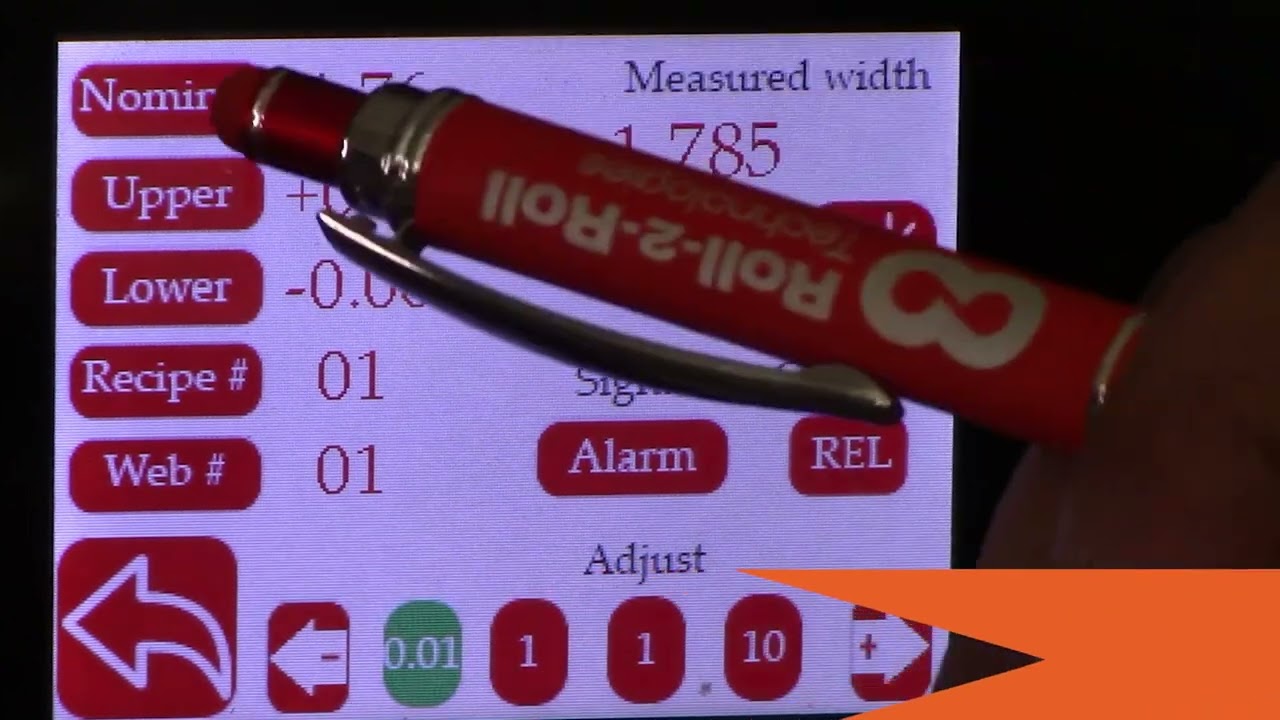
This video show how to access the web width measurement dashboard on the SCU5 controller. This dashboard is enabled by a built-in web server on the SCU5 controller. And the dashboard is only available with the following industrial ethernet protocols:
- EtherNet/IP
- PROFINET
- Modbus/TCP
For more information about SCU5 controller please visit: https://r2r.tech/products/roll-2-roll-controller
Transcript
Show full transcript (474 words)
apart from looking at the dashboard with the IP address set like this we do have another web page on some of the controllers that are specifically for width measurement applications and this dashboard is for General prototyping it's got the sensor and fault information and things like that but for customers that are looking to log data for width measurement application they can go into another dashboard and that's located in the same website address or the IP address and with the extension width.htm so it looks like a similar kind of dashboard the only difference is that this is specifically designed for width measurement application so as you can see on the top it shows you the width of the web directly in inches and if you want to look at it in millimeters you can just go in and click that it's going to give you that width in there and if you have the web moving back and forth you can still see that the width is being measured and recorded everything is similar to the previous dashboard except that it's catered more towards width application and you can also set the same thing to download the settings and save it and things like that one additional thing that we need to keep in mind when we have this dashboard is that the data is actually coming from the controller and there is a web server that is running on the controller so you can have multiple instances of the dashboard so you can actually go in and open another one and have two dashboards at the same time and whenever you are setting up to download the data again you need to keep in mind that as long as the web browser is open it's going to keep doing everything if the web browser is closed or if you refresh this page on the web browser the data is going to start over every browser tab or every browser tab is an instance and the web server is serving the content and then the JavaScript on the web server is executing it and displaying the content on the web page that's the only thing that you need to keep in mind is that if you want to log the data you need to have either a dedicated computer where you can set this up and then nobody is going to disturb it that way it keeps recording the data automatically and other than that it's a quick prototyping tool to see how our system performs and what the parameters of the system are in real time once again thank you for watching and we'll have please subscribe to our Channel and we'll have more videos that talks a little bit more detail about different things from our product