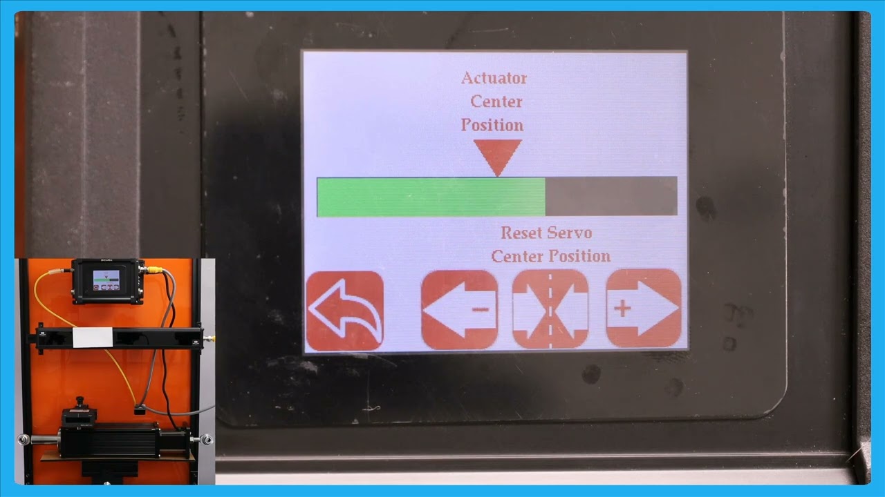
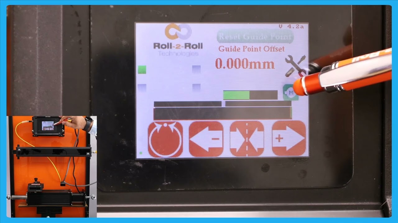
In this episode, we explain the functionality of an enhanced operator interface that provides a larger view of the actuator position. This feature is particularly useful when operators are working at a distance from the controller, allowing them to make precise adjustments without the actuator reaching its limit. The video demonstrates how the web guide operates in automatic mode and explains the benefits of being able to view the actuator bar from different parts of the machine.
Transcript
Show full transcript (211 words)
one of the reasons why we have this icon where the operators can see a the view of the actuator position is those scenarios where an operator farther away from our controller and they want to make some subsequent adjustments to the position or essentially the date Point using the the mode operator interface but they want to make sure that adjusting the G point doesn't make the actuator to reach its limit that's all of the reasons why we have that right now the web guate is in automatic mode and the web is staying there it's not moving but if I move the web guate you can see that you can the actuator bar changes if this is just a bigger view of what we had in the home screen and the reason why is uh a bigger view is allowing The Operators to see this interface from a longer distance while they're making adjustments to other parts of the machine so that if the actu reaches its limit it's pretty evident and they can make adjustments to the other part of the machine so that it doesn't guide doesn't lose its stroke during guy this button you can reach it either in automatic mode or in manual mode
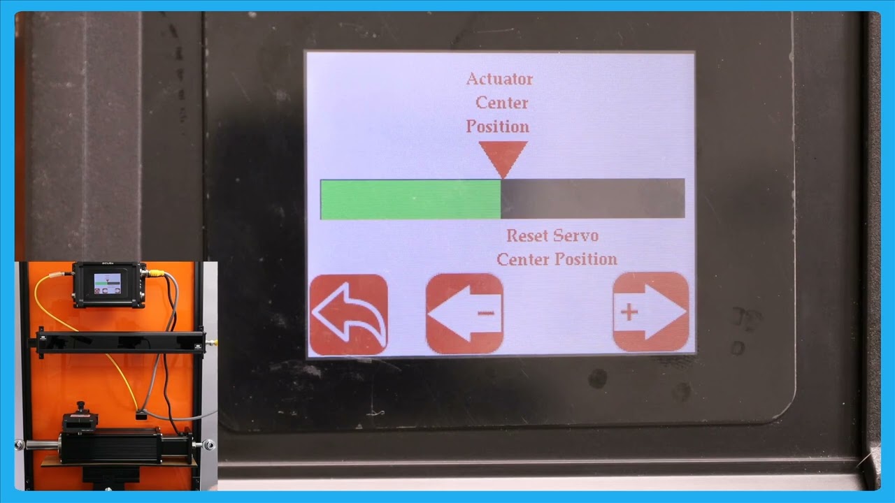
In this video, we explore an important feature of the SCU6x Controller related to the servo center position. We discuss a scenario where operators are not permitted to change the servo center position and how the controller can be configured to lock this setting. By clicking on the motor icon, operators will only be able to see the jog left and jog button options, while the reset servo center button will be hidden.
Transcript
Show full transcript (135 words)
so one other option that we have is that if if the operators are not allowed to change the servo Center position then in that scenario the controller can be locked in such a way that the operator cannot change that simple Center position then if you click on this motor icon now it'll only show you the jog length and the jog button and it won't show you that reset Servo center button so the operators could just view the actuator position and not be able to reset the C Center position so that's the difference between having n enable and disable this is about moving the actuator manually to facilitate loading and unloading the RO but the real thing with our system is basically it does guide the we automatically to its Desir
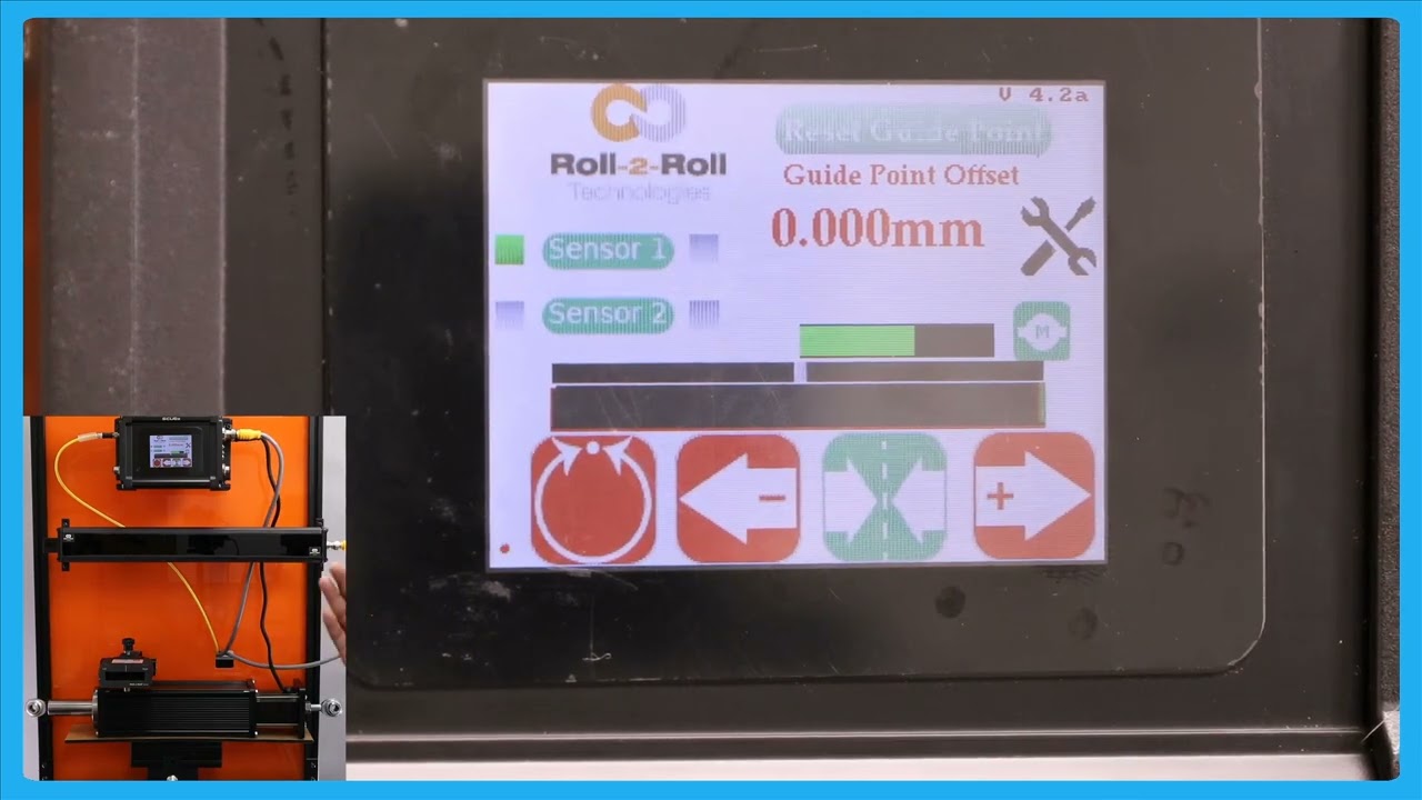
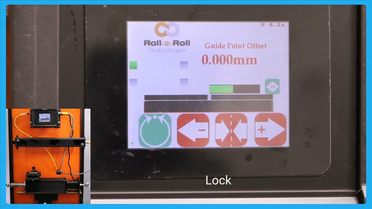
In this episode, we'll explore the functionalities of the SCU6x controller, focusing on the different operations of jog buttons, and the servo center feature. We'll explain how the servo center button positions the web guide in neutral and how this differs from the momentary jog buttons. The video also covers indicator states for the servo center operation, including how it transitions from green to red. Future videos will detail more about the methods for servo centering, including using electronic limits and physical proximity sensors.
Transcript
Show full transcript (341 words)
now if you want to put the web guide in Servo Center basically means different things for different types of web gues but essentially putting the web guide in a newos so that it has enough stroke to go on either side um of the servo Center position then you can press this button and this button uh it's a single press button and when you press that it will bring the web guide or the actuator to its home position or what we call as the zero position so one difference between the jog buttons and the servo Center buttons or that these jot buttons or what we call as momentary buttons that means that you need to keep pressing there for the actuator to keep jogging as soon as you let go the actuator is going to stop jogging in that case both of them are like that um Ciro Center is more like a push button and it it will actually tell you the Stak in which it is there for example if I johned it and then if I put it to server Center this is in the servo Centric state so it's going to be green and until the servo center operation is done it will stay green and once the operate operation is done it will turn back to Red so there's no need for us to keep pressing that button it's a one time push button C so click just to give you this again when you press the servo Center it's going to uh bring the actuator to its home position once the operation is done once it reaches the home position it's will turn back to um reding there are different ways in which we could do the servo centering operation which will be handled in a future video essentially depending upon whether we are just using an electronic limit or if we're using a physical proximity sensor to do that so those are for the jog left Jog and turbo Center
In this video, we introduce and explain the automatic web detect signal feature of the SCU6x Controller. This functionality ensures that the actuator stops moving when the web breaks, even in automatic mode. The video illustrates how the actuator guides the web back and forth and demonstrates the lock on lost edge feature, which holds the actuator's position if no web is detected. This feature is crucial for preventing disruptions in operations when re-threading the web.
Transcript
Show full transcript (199 words)
so one other feature that we have is that we have an automatic web detect signal in a previous video we talked about this which is that web detect signal we can use that information to stop the actuator for movie even while it's in automatic mode if the we breaks so just illustrate that I'm going to show that and stting the web Maring toward and you can see that actuator position but if the web breaks and there's no web in front of it then the actuator stay stays put and this is what we call as lock on Lost Edge essentially a functionality that ensures that the actuator doesn't get cocked to one side or the other if there is no web in the field of view of the centor and as soon as the web comes back it's going to start dating it when there is a web break it's going to start and hold it position and this is essentially for detecting the uh web Brak and then making sure to stop the actuator in its current position so that it doesn't disrup the the operation once the direct web is started back in
The second part of the SCU6x Controller Tutorial explores the SCU 6X controller with a focus on its functionalities and capabilities not covered in the first part. Learn how to navigate the home screen, perform manual jogging, set servo centers, and operate in automatic web guiding mode. Discover the safety features, guide point adjustments, and the differences between edge guiding and center guiding using sensors. This tutorial provides a comprehensive overview of the controller's interface and its operational capabilities.
Transcript
Show full transcript (3301 words)
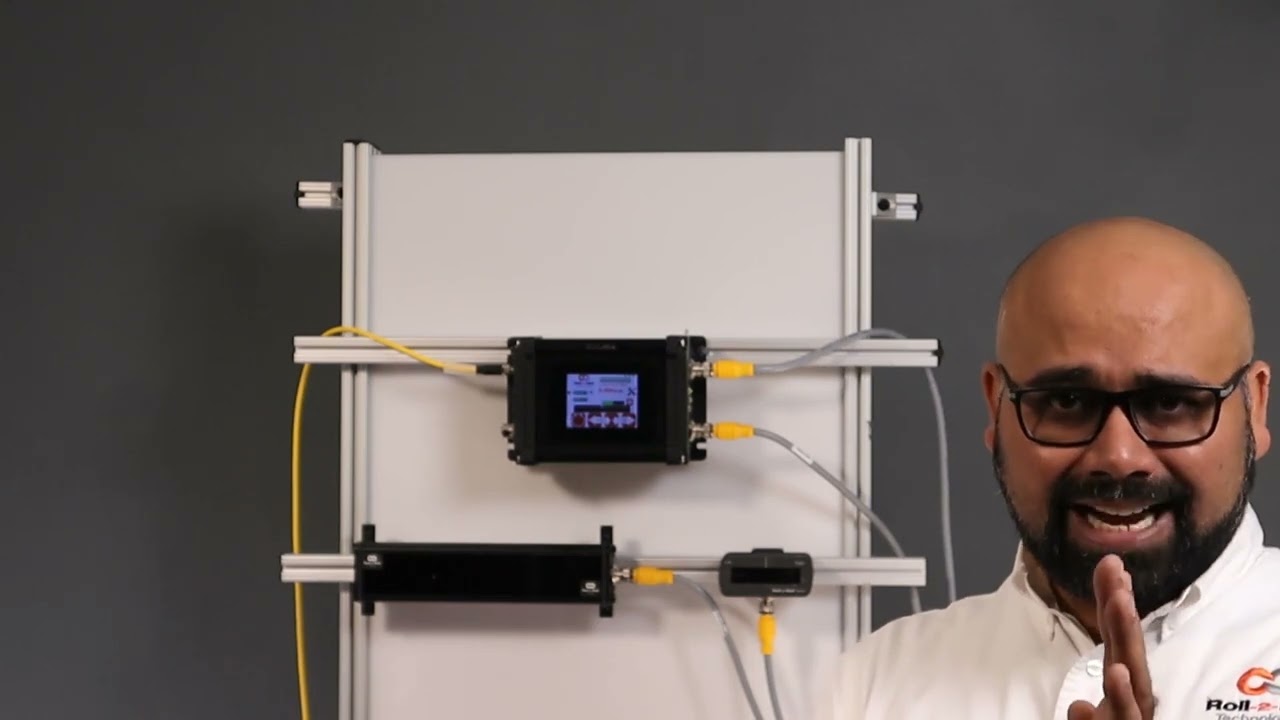
hello everyone this is Aran sadri from Roll tooll Technologies today we're going to look a little bit more about some of the other functionalities on the home screen or the operator interface screen and specifically related to actuators so what we have today is our SCU 6X controller and this is SCU 6X MD and we have one sensor connect Ed to it then in the motor port we have an actuator connected to it right there seu 6X MD and there is another option seu 6X mxd both of these options are allowing us to connect different thrust actuators for example this particular one Su 6X MD has the low thrust option where we have an actuator that can drive up to a about 300 lb fors of trust anything related to intermediate web guiding this will be the actuator for that this particular actuator can draw up to 4 amp of Curr when we go to a higher prust the part number is going to be a little bit different it's going to be SCU 6X mxd where the X relates to the extra in that we need and that particular one can drive up up to about 500 lb of crust so a shifting stand with the total weight um of though more than about 5,000 lb can be driven with that actuator the only difference would be the connector here would be a little bit different on this side now it'll be a high thrust a high current connector and then for that particular actuator we would also need a different power in the Dual re power input will will have 7 amps up to 7 amps for that we also can do up to 48 H DC everything that the operator need should do on a day-to-day basis can be done from the home screen for example things like putting the web guide in automatic or manual joging the web guide back and forth and then putting the web guide in the C Center mode the first and foremost three with the with regard to the actuator is this actuator position bar this bar is going to indicate the position of the actuator in this position is the electronic position that is being read by our driver right now the actuator is in the middle as we jog the web guide you should see that actuator position to be changing and then there's also visual indication of when the actuator is getting new near to its extreme position and that's indicated by this um yellow bar and then if you keep moving it turns red which means that there's really not much left in the actuator position so this is indicating that it's reaching its stroke Lane now in terms of the stroke of the actuator these are all electronic limits that we have in the controller in subsequent videos we will talk about how one can change those limits based on what the actual actu stroke T takes like that so this is the if I press this one you should be able to see that go draw the left and it'll do the same thing if it goes to a certain position where it's getting closer to its extreme it's going to be yellow the keep going called the dead red and then if it's off the read even if the actuator presses this button now nothing happens and that's because the actuator has reached this limit there so it will not move in that direction however it will move in the other direction so that's the actuated position more then we saw the jog left and Jog right command there now if you want to put the web guide in Servo Center basically means different things for different types of web guyses but essentially putting the wind guided a U pro position so that it add enough stroke to go on either side um of the servo Center position then you can press this button and this button uh it's a single press button and when you press that it will bring the web guide or the actuator to its home position or what we call as the zero position so one difference between the jot buttons and the servo Center buttons are that these jot buttons or what we call as momentary buttons that means that you need to keep pressing there for the actuator to keep jogging as soon as you let go the actuator is called a stop joging in that Cas both of them are like that um Circle Center is more like a push button and it will actually tell you the Stak in which it is there for example if I JN it and then if I put it to server Center this is in the servo Centric state so it's going to be green and and until the Sero center operation is done it will stay green and once the oper operation is done it will turn back to Red so there's no need for us to keep pressing then button it's a one time push button C so click just to give you this again when you press the servo center it's going to uh bring the actuator to its home position once the operation is done once it reaches the home position it's going turn back to um red again there are different ways in which we could do the servo centering operation which will be handled in a future video essentially depending upon whether we are just using an electronic limit or if we're using a physical proximity sensor to do that so those are for the jog left Jog and turbo Center one other thing that we have is basically this actuator position bar if you press that motor icon on the home screen this let you see a bigger view of the AG regor position K in this case if the web CAG moves back and forth you can see that actuator bar will move back and forth one thing to note about this Servo center button is that this has a different functionality than what it is in the home screen so we recommend that you take a look at the subsequent videos about this functionality before using this so one other option that we have is that if if the operators are not allowed to change the servo Center position then in that scenario the controller can be locked in such a way that the operator cannot change that simple Center position then if you click on this motor icon now it'll only show you the jog length and the jog button and it won't show you that re reset Servo center button so the operators can just view the actuator position and not be able to reset the C Center position so that's the difference between having that enable and disable this is about moving the actuator manually to facilitate loading and unloading the roll but the real thing with our system is basically it does guide the we automatically to its desired okay this is about moving the actuator manually to facilitate loading and unloading the r but the real thing with our system is basically it does guide the we automatically to its desired position so just to show you that let me present the we put the web guide in automatic mode so as you remember that the gray bar in the middle is basically our G point and if we are on one side of the G point the aerators will move one way if we are the other side of the G point the actuator for M be way and it's that's out it's stating the web and then the actuator position bar indicates what the stroke of the actuator is and obviously once it reaches its stroke it doesn't matter how much error we have the accelerator is not going to move in that direction but if the eror F on that direction then the actuat is willable and he that in for BL so this is the automatic feature of our web guing system and right now I'm using a single edge to gu the material and it doesn't matter if I have one Edge or two edges it will do the same thing so one other feature that we have is that we have an automatic web to Tech signal in a previous video we talked about this which is that web detect signal we can use that information to stop the actuator for movie even while it's in automatic mode if the we breaks so just illustrate that I'm going to show then and sping the web Ming toward and you can see that actuator position might keep the web braks and there's no web in front of it then the actuator stay stays put and this is what we call as lock on Lost Edge essentially a functionality that ensures that the actuator doesn't get cocked to one side or the other if there is no web in the fielded view of the CER and as soon as the web comes back it's going to start dating it when there is a web break it's called start and hold it positioned and this is essentially for detecting the uh web break and then making sure to stop the actual in its current position so that it doesn't disrup the the operation once the TR web is turnning back in okay in a previous video we looked at the G Point offset basically how to reset the G Point again that is useful when you have a white sensor and you uh present the web like different notations so just to go for that one more time here I've got a white sensor here and the web is positioned at some point I'm going to go in and reset gate Point except that's there and if I put the we p in automatic it's going to stay in that position and if I need to change that dat point to a new location when it's in manual and we can still do that the we isit this new location and I'm going to do the reset cway accept and when I put it in auto in scr the actuator is staying in position because the web is at the night Point location and if I move the web to one side part the other it's little stop it's going to die with respect to that c one that's the briet cake one now there are situations where you are guiding the web you got it at the SP but you want want to make a fine adjustment and with the traditional sensors there might be something like a micrometer and an operator needs to reach in and try to adjust that screw on the micrometer to move it back and forth to do what is called as a fine dat point adjustment so think of it like a lamination process you got the wind align guiding but you want to change that gate point just a little bit you don't want to make too much of an adjustment and you want to do that while the Wim is running and that is what we call as a fine gate point adjustment how to do the fine gate point adjustment right now the G Point offset isus 119 mm and if I want to change that just a little bit then I if I want to increase that I can press that increases that the web guide is not going to move until it goes away from the B so just to illustrate the SP thing now it reach the limit for the dead man and it's continuing there that's our fing point adjustment so this allows you to be able to M uh make very fine adjustments to the guide point again the plus arrow allows you to increase that gate point and minus Arrow allows you to decrease that gate Point that's what is called it a fine gate Point government and this adjustment can be done only when we are in automatic mode and then each press of B will take1 mm I think that's what it looks like1 mm to move the gate plan one of the reasons why we have this icon where the operators can see of either view of the actuator position is those scenarios where an operator is farther away from our controller and they want to make some subs sequent adjustments to the position or essentially the DAT Point using the M operator interface but they want to make sure that adjusting the gate point doesn't make the actuator to reach its limit that's one of the reasons why we have that right now the web guide is in automatic mode and the web is staying there it's not moving but if I moved the web gu you can see that you can the actuator bar changes if this is just a bigger view of what we had in the home screen and the reason why is uh a bigger view is allowing The Operators to see this interface from a longer distance while they're making adjustments to other parts of the machine so that if the actuator reaches its limit it's pretty evident and they can make adjustments to the other part of the machine so that it doesn't the guy doesn't lose its stroke uh during guy this button you can Beed either in automatic mode or in manual mode okay one other feature in terms of resetting the G point hset on that we have is there are some occasions where you want to reset it to zero and this has to be done with extreme care and only people who know what they're doing should be able to do this and that's because this is very powerful and changes the date Point immediately so there might be some occasions where you want to absolutely reset pick 8. to0 the best way for us to do that is while it is in automtic did you press the servo center button it's going to show you that hey you want to reset the G point to zero do you want to accept it obviously if I accept it the web visit different location it's going to go all the way to one side the actuator is going to go all the way one side because it's trying to correct for the we position again when you're in automatic mode if you press this Servo center button then it would allow you to reset the G point if I press accept the T point is going to be in the middle now Bally the actuator is newly because it's trying to bring the web to its um to the P Point reference that's the way in which you could reset the K point to Z one other thing that happens when we put the web guide in automatic mode is that this tools icon is going to disappear um I'll do that and you can notice that the proven automatic the tools icon disappears so essentially when the web guide is in automatic mode the operator cannot go in and change any parameters related to the edge Center or contrast or anything related to the speed the gate none of those parameters could be changed while the webite is aide just a safety just so that we don't intentionally cause any cor when the webc isn't so that's why that one is the only screen that the aerator can navigate to is going to be this screen and that's going to show you the actuator position in a bigger view the operator cannot go into any other screen while in automatic mode the other thing that you're going to notice when the web guide is in automatic mode is take a look at these sensors so I put it in automatic mode the buttons so those buttons are disabled again same idea when you are an automatic we don't allow the operator to change the orientation of the sensor so if they can't enable or disable the sensor they cannot switch from one sensor to another sensor all of these things have to be done a pror before they put it in the automatic one and then again reset dat point if you put it in automatic mode that disappears so they won't be able to make any big adjustments to the G point the only exception to that is to reset that gate point to zero as the only that they can do and that's the reason why we say that when you do a reset CR point to zero to be really careful um and do only and that's the reason why we have that accept button so if somebody presses St by the St we don't necessarily have to take that command unless the operator intentionally presses accept if it doesn't press the accept button then it'll go back to the previous gr point so the next thing that we're going to look at is we showed how to do Edge guiding with a sensor now we're going to do how to do cting with the sensor so I'm going to change this orientation sensor orientation so that sensor one can detect voltages of the web and that's what it it's detecting and as you remember from our previous video when we do c and the guide the ref reference for the web is not based on one Edge actually based on the two edges so that's what is presented by this green bar so if I move the center line of that web to this green bar to this point box act and then put it in Auto then when that centrer line changes position that's how we're going guided essentially Center guide so what is the advantage of Cent gu is that when you hand weight changes you don't have to move the sensor as long as your G Point offside is the right loation so for example if I put another web that's wider you can do a on the Fly wi change with one to another web wi and it will automatically guide and you wi in a C position and that's one of the biggest advantage with a center diing solution is that when the wit changes let's say it have some varability in your brid your web will always be presented to the center line of the machine as long as the center as long as the sensor is set up properly then you can bring it to that Center Line position with respect of the quarter in or half an inch web with L so in terms of Center guiding Center position this represent by the green bar and then the web guide is going to keep that Center position um I'm moving the actuator back and for so that green bar aligns with that gray gray P point and cence as it should so that's the main difference would be Edge tiing and Center Tiding again you still have that option of web Brak so the web braks it will stop actuating and it will start back actuating but the web this dressing and then obviously it's going to do it it's going to stop until the web reaches its B Point reference if the WID changes doesn't matter as long the red WID the Cent line that so that's Center D with with a single sensor
Comprehensive Guide to SCU6x Controller: Home Screen, Sensors, and Troubleshooting Tips
Transcript
Show full transcript (3934 words)
[Music] hello everyone today we're going to take a deep dive into the SCU 6X controller I have a a demo setup here with the um SCU 6X controller in the back and a couple of sensors connected to it what we're going to do is look at the home screen or the main operator interface screen and we're going to look at what are the things that are available in that screen how an operator can use to kind of understand what's going on with the system and also use it for troubleshooting purposes and things like that we have the seu 6X screen right here so I'm going to zoom in to that and we're going to do a deep dive into all the buttons that are available in the operator interface we'll talk a little bit about the connections as well and then I'll finish up with what are some of the common troubleshooting ideas or tips based on the information that is available on the home [Music] screen first and foremost thing that I want to point out is what we call as the heartbeat LED this is basically the bottom left hand corner and this particular LED is blinking between red and green in the SCU 6X there's actually another led a physical LED that's available on the side which is labeled B zero and that will also blink between green and no no light so we call it a heartbeat which means that this is very critical and we want to make sure that this led is blinking all the time so this is again one of those things which is used for troubleshooting purposes if you call us and say hey something is happening nothing is working when we touch the um operator interface the first thing that we're going to ask is that hey is this heartbeat LED blinking and what it is indicating is that there is the program the motherboard is running and the motherboard is communicating back to the operator interface and and the motherboard if there is no communication between the display and the motherboard then this led would stop blinking so that's a good good indication to say that there's something wrong with just the touchscreen operator interface the motherboard is still working fine [Music] the next thing that we focus on is going to be this top right hand corner it says B2 4.2a it's kind of hard to see for you but believe me there is a firware number there so that is basically the firmware number or the firmware version number for this particular controller this is another common thing that you would ask especially for troubleshooting purposes what that fir number and if that doesn't give us enough information we do also have another shmer number on the back which is printed on our product label and that is for if we want to get deep down into it so when do we change these firmare numbers on the top here uh anytime there is a significant change where we are doing a bug fixing we would change that firware number and also anytime there's some UI changes so any anything with related to the buttons adding a new screen or removing a a different screen we would change that firmware number so in general we don't remove any features we only add features to our system so most often if you have a product manual that says version 4.2a most likely it will be applicable to a version 4.1 or 4.0 as well another note if you're familiar with our seu 6X controllers or if you are familiar with roll to roll Technologies we had an seu 5 controller before and now we have the SCU 6 the SCU 6 all start with version 4. something and SCU 5 all start with version 3. something that is the firm number the next thing we want to focus on is this bar right there which is called as the web position indicator and uh depending upon what sensor we have connected the bar will show the position of the web and so for example if I put the web there you can see that it's showing that position and the way the web moves depends upon other parameters but that's indicating the web position another key thing on the bottom left right above that heartbeat LED is called a web detector indicator right now you can't see anything it's gray but when I present the web there it turns green when I take it off it's gray so that is what we call as a web detect indicator when when you are under normal operating conditions that uh should be green all the time I'm going to make it kind of flicker back and forth just by moving the web closer or farther away from that sensor and you don't want that to be blinking like this that's not a good sign and then the first thing that we are going to look at is is the sensor installed properly is there something in the background on the sensor that we need to consider and and is it angled properly so that it's not picking up something and losing the web position both heartbeat and web detect indicator are two important things that are available on the home screen on the SCU 6X we have these two buttons which say sensor one and Sensor 2 and essentially what it is is that these allow us to configure our sensors however way we want our sensors are one-sided which means that we could have the web come in from either direction and this is what we call this a sensor orientation so it could come from this way where it's coming from the right to left or it comes from left to right so our controller can handle either of those conditions we just need to be able to tell it how to do it for all our sensors the orientation is defined this way for the 48 mm sensor there's actually a label that says left and right so if you look at here you would see that there is a right and a left indication that means that if I I pressing a we and I see that left label that means we are looking at the left edge of the web if we come this way we are looking at the right edge of the web and that's how we know the orientation for the 48 mm sensors for anything from 96 to 960 the orientation is this way where that keyb comes out that is going to be our right and where the cable is not present that's going to be our left so this region is going to be our right and this region is going to be our left so if we present the we and we see the left Edge like what I'm showing here so that's going to be configured as a left Edge orientation and if we present the web like this where we're looking at the right edge of the web then that's going to be the right Edge so these bars these green squares are indicating how that particular sensor is Con configured if you press that once it's called a todle between the states I'll do that again so the the four states that are available are no sensor which is what this is both those LEDs are turned off if I press it once sensor one is configured as left left sensor and that's what this is and if I press it another time it will go to Center sensor which means that you have both edges of the web if I press it one more time it's going to go to the right sensor and if I press it one more time I can disable the sensor all together so that's what that button is allowing us to do is to configure the orientation of the sensor whenever we press that button one key thing to note is that if we have this sensor C able disconnect it then this button will only have two states one is enable and the other one is disable because it's either enables the sensor or disables the sensor the controller automatically knows that there's no sensor connected to it so it's not going to toggle between the states it's just going to reable it and disable it so when I reconnect this back in then we have the ability to get all four states right now the sensor is disabled I have it connected now it can go to the left sensor Center sensor right PR disable likewise you can do the same thing for the sensor to and for now I'm going to disable both sensors and just enable right sensor as left Edge the sensor button allows the operator to go from one state to another [Music] state so one of the key things why we have this functionality is that you want the operators to have the flexibility to move the sensor from one side to another side and have a simple couple of steps to switch from one edge of the web to the other edge of the web there are scenarios where when they're running one job they want to write on one Edge and when when they're running another job they want to run on another Edge also we have the reason to enable and disable the sensors because there are situations where they might have two different locations where they are guiding the web and for two different products so for example let's say they are running uh a 20in wi web for one job and a 30in wide web on another job into of moving the sensors from one Edge to the other Edge when the wig changes The Operators can just have two sensors installed at two different cross machine Direction position and then just enable that sensor for that job for one time and then enable the other sensor for the other job at the other time our controller will automatically figure that out whatever the sensor is enabled or how many other sensor is enabled that's what is going to be used for guiding purposes and it will take care of everything else automatically so that's the reason why we have the ability to enable and disable the sensor there are also applications where we have one actuator guiding the web and there might be a scenario where we want to guide the web with one sensor in One Direction and the other sensor in another Direction these are commonly seen in machines where the web can can go both in forward and reverse Direction especially in an unwind or a rewind you can have it configured where in One Direction the the system behaves like an unwind with a sensor installed on the fixed machine frame and then when it goes in the backward Direction the same system behaves like a rewind where the other sensor would be installed in a chasing kind of configuration in those cases we can switch between the two sensors pretty quickly just from the home screen without us having to navigate to multiple screens to enable or disable the sensor so that's the functionality for the sensor orientation buttons so I will present the web right now and we're looking at the left edge of the web and as you can see that the white region in the web position indicator is representing the web and the black region is representing the uh backdown or Mo so as I move back and forth if I have the Lage configured for the orientation then as I move from right to left the web position is going to increase from right to left just like what you see on the scen if we change that orientation to right the bar automatically switches and it goes in the other direction just like what beings right I'm going to disable it and enable this sensor but I'm going to do a center orientation for that this means that we have a a sensor that is wide enough that it can see both edges of the wi the first thing that you're going to notice is that there is a green line in the middle and that line is indicating the center position um of f sensor and when I present a WEP here then you're going to see both edges so that that the left side is dark the right side is dark the middle region which represents the web is going to be white and then the green line is the center line of the we and that's what it's showing there it's being moved from left to right so when we do Center guiding the reference or the edge position for that guiding is indicated by this green line right there so in this case it's Center the controller automatically knows that if you set it in Center then it needs to look at the middle position of the web if we put it back to left mode it's going to look at the left Edge and the green line is still there and it's kind of hard to see but it's at the leftmost point of the white region and that's what we call as um The Edge position so this is what is used for control now in respect to of what we have it does change my Edge position and also notice that I only have one edge of the web or I have both edges of the light break here but it's only looking at the left Edge so when I have this uh small piece of paper where I see both edges if it is configured for the left Edge it will only pick up the left Edge and if I do Center you can see both edges and if I do right it'll only pick up the rage and that's how it works so it doesn't matter if the web is wide enough or wider than the sensor field of you how we configure the orientation will dictate what Edge the is used for guiding or uh control furnaces so there are situations where we would have to use two sensors and uh if the sensor is not wide enough or the web is much wider than our sensors then um we would have that scenario I have this sensor two which is this sensor I have that configured for left Edge in sensor one I have that configured for Frid day and then now if I present the paper that this partly seen by One sensor and partly seen by other a sensor then we're going to see that and then again the the green line indicates the center line position and then the right edges and lighter the left edges indicate the edges of the W one of the things that I want to point out is that in uh normal situations we will always ask that uh when you do Center guiding with two sensors that you use two of the same sensors with the same measuring range and same resolution it just makes it easy and it avoids any confusion here I just wanted to show that it's possible to use different sizes of sensors when you do centri guiding uh what where does this confusion come from just to show on the screen what I mean by that we have one sensor configur to left and the other sensor configur to the right and when we do that the screen is going to be split up into two regions or the web position indicator is going to be split up into two regions if I present the web on just one sensor so I'm presenting it on sensor one which is config as right sensor you can see that only that great half is being updated likewise only the left half is being updated and then when I have a web wide enough it sees both sensors then the portion of the left half corresponding to the left sensor and the portion of the right half corresponding to the right sensor is only going to show up there so the conclusion arises mainly because we have one sensor that is almost six types or or eight types wider than this sensor but we only have the same 50% viewing area on the top so when we move just a little bit on the bottom sensor it seems like it's moving a lot whereas when we move little bit on the top the the right left sensor then it seems like it's moving a little but in reality it's moving the same amount but it's just that on the screen we don't have we're not scaling that based on the two different sensors range so that's the difference so we covered the main things with the sensors in terms of the orientation how the web position is indicated how you get the web detect signal and things like that one other key feature that we have is what we call as reset G point this enables our operators to switch from one width to another width without moving the sensor itself in a traditional application where you have a narrow band sensor that takes about 6 mm that's looking at one edge of the web if you change from one web WID to another web WID then what they have to do is they have to physically move the sensor that's like having a rail and move it there and the other thing that they do is that they might have to do a they they might have a micrometer or a fine adjustment to move that sensor just a little bit based on what the guide point is all of these things could be done digitally from our home screen and that's what I'm going to show show you next to show the gide point adjustment uh I have once in are connected to the controller and enabled and it's set to the left sensor configuration so you can see that when the web moves here it's the left sensor configuration now what we want to do is we want to change the guide point let's say we are running a different job at a different location instead of moving the sensor we want to change the GU point so let for example this is the web and we have traded the web and this is the correct location or this is the ideal location where we want the new reference to be what the game point to be all that the operator needs to do to reset to this gra point is to press that button and accept and that will change the gr point so the gr Point offset on this home screen is showing us how far away from the middle is the current gate point and right now it's exactly in the middle of the sensor speed with view in t zero and Visually it's also indicated by this bar right here and this is exactly in the middle of the field of view of that now if we go to the left of the guide point and let's say this is our new reference and the operators instead of moving the sensor they can move the DAT point so all that they need to do is press the reset G point and say accept now we can see that the DAT Point number moved there and also this dat Point bar move there you know so that one more time let's say they want to use this current web position as the reference then press reset take point and accept and it moves there so this number right here the G Point offset what is showing is that what is the offset from the middle and and that is indicated in the so that's to reset the gate point now if you really want to move the gate Point without the web can still do that by grabbing that and doing that and we call that as a cross gate point adjustment so you can just grab that reference bar and move it to whatever you want and press except and that will do that so that's what we call as a gross great point adjustment and then we don't allow you to change the guide point all the way to one side like that so if we do that it will go only to about a certain amount and that's just for safety purposes and then just to be sure that somebody doesn't intend to do something what we also do is that if somebody press this button and let's say that it it shows the reset gate point to a new gate point and if you didn't intend to do it all you have to do is just leave it alone for a little bit and then that will automatically reset unless you press accept any change to this accidental change it will show that the the current or intended gate point is minus 16.7 but if you don't accept it it will go back to its original gate Point reference whatever you had it for so just to avoid any accidental changing uh we do that and it's the same thing with this reset gate point if you press that button unless you press the accept anything that we do here is not going to change the gate Point unless somebody intentionally says that that's what they want to do we want to make sure that we have everything set up uh properly where we're able to see the web now in the following we will look at how to set up the controller for guiding or actuation the operator can use that uh home screen to put the web guide in Auto put it in manual and also be able to manually jog it left and right and then also do any Servo centering operation or things like that that's what we're going to see next so I do have a couple of things set up here so I have one sensor that is set up to look at the left edge of the web that's shown here since the one is connected and it's set up to look at the left edge of the web and in this particular placee I don't have an actuator connected but I can still show most of the items there through that interface so these buttons on the bottom these are the buttons where somebody could put the webc an auto or manual or jog or Servo Center we'll go through this one by one the Jog and the servo Center buttons or what we call as momentary [Music] buttons this one is basically Auto or manual when it's in red it's in manual mode and if we press it and if it changes to Green it's in automatic mode and um as you can see it's seeing the web right there when I move the web you can see that the web is oscillating here and these are J left and Jog right and then the S Center e

Exploring the SCU6x Plug and Play Operation. Understanding Plug and Play with Roll-2-Roll's SCU6x Controller Join Pedro Velasco from Roll-2-Roll Technologies as he demonstrates the simplicity of their 'plug and play' SCU6x controller, ODC48 sensor, and actuator system. This video covers the setup process, including how to properly connect and power the components using industry-standard connectors. Pedro explains the function of the ODC family sensors, highlighting their ability to detect various materials without the need for calibration.
For a complete overview of web width measurement with Roll-2-Roll® Sensors and Roll-2-Roll® Controller please visit this page: https://r2r.tech/articles/web-width-measurement-and-monitoring-applications-and-technology
For more information about the SCU controller please visit: https://r2r.tech/products/roll-2-roll-controller
Transcript
Show full transcript (1228 words)
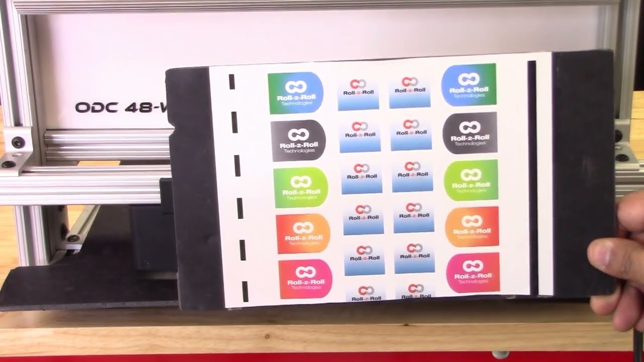
continuing along the lines of measuring the width of the web based on the contrasting feature in this video we're going to look at how we can measure the width based on some printing or contrasting feature on the web with two sensors so I've got a sample here with a whole bunch of features on the web not just the edge of the web the left side has a intermittent line of a certain width and then the right line right side has a solid line and then we have some labels with different edges with gradients and things like we can use any of these features to be able to measure the width of the web we don't necessarily need the edge of the web and as explained in the previous video These are relevant for certain applications where you want to measure the width of a coating or the width of a printed feature that might expand or contract differently than the edge of the web and then our sensors have the ability to be ability to do that so let's go into the controller and see how we can set this up we want to First make sure that both sensors are enabled and I've got both sensors enabled and I'm going to the operator sensor screen and we've got the sensor one and the Sensor 2 image as a first step what we are going to do is we're going to teach the teach Sensor 2 to look at that intermittent line and sensor one to look at the solid line and use that information to measure the width of the web so let's go to Sensor One sensor 1 has the solid line so we want to pick that line so I'm going to go in and pick the line mode and pick the feature that I want that's the solid feature that I want logged in on it now go into sensor 2. this is the intermittent line so if I move the web or remove the material you can see that the line disappears comes back in so I'm gonna pick that feature right there lock it in and then we have locked both the features but we don't know the distance between the two features so if we already know what the distance between the two features are then we can enter it so let's say it's eight inches is the distance between the two features I'm going to go in and teach it so the teaching procedure what it does is it teaches the controller to know that to know the distance would be in the two sensors if we don't do that then the output measurement is not it will be it will be proportional but it won't be the measurement so I'm going to go in and teach now I've got that measurement taught in as you can see on the web browser that the measurement now has updated to 8.002 inches and what I'm going to do is I'm going to move the sensor so maybe we can have a picture and you can see it there I'm going to move the sensor so that you can see how that width measurement changes oops there's the width measurement and when I move the sensor you can see that the width increased because I moved the sensor outside and now I'm going to move the sensor inside and you can see that the width goes down this way you can pretty much teach the controller to pick up any feature that you want and have the ability to track the width of the two features and teach the controller for the distance would be in the two sensors and then log the data we'll also look at how we can do the same thing with a different type of feature so we'll go into the controller operator sensor screen and then this is the intermittent line sensor so I'm gonna make sure to try to teach it to the edge of the label so I've got that label there put it on auto and I want to be able to teach that so we want to come in from this direction and pick that edge of the die-cut label there and I'm going to move this Sensor 2 and do the same thing sorry sensor 1 and do the same thing so this is the black line and this is the edge of the die cut label so we want to teach it to that want to go to that mode and pick that edge of the die cut label teach it to that teach it to that we need to make sure that this turns red and all the other features goes away that's when the controller says that the feed feature had been taught if it doesn't happen then the width will not have an output also what happens if we don't have it again if we go back and teach the distance between the two sensors so let's do that to be the same eight inches and if you go back into the web browser then you can see that's the width and if I move the sensor and you can see that on the top right hand corner if I move the sensor then the width increases or decreases so pretty much any feature that we could teach for in the contrast mode can be used to track the width of that contrasting or the combination of the contrasting feature one more thing I want to mention is that we want to make sure that the teaching is accepted by the controller if the teaching is not accepted then the width will not get recorded properly so for example if I go into the sensor screen go in here and then let's say the teaching was not accepted if the teaching was not accepted it's going to look like oops it's going to look like this even though it picked up the contrast the teaching is not accepted and if we go back to the home screen the width is going to be zero this is mainly because that in order to measure the with the contrast mode both sensors the contrast needs to be picked and thought so if we go back in and teach that contrasting feature for sensor one Sensor 2 also has that already and if you go back to the home screen you're going to see the width measurement and if you go back to the web browser you should also see that with the measurement there um that's essentially how we would set up the controller for web width measurement with two sensors and both sensors are in contrast mode and tracking a contrasting feature on either side of the web concludes our presentation about width measurement with either one sensor or two sensors with either Edge mode or contrast mode we also looked at the different outputs that we received from the controller with respect to analog digital and ethernet and with this you would be able to apply our products to a multiple different applications hope this information was useful and please subscribe to our Channel and for more information about our products and how they can be used in your application
For a complete overview of web width measurement with Roll-2-Roll® Sensors and Roll-2-Roll® Controller please visit this page: https://r2r.tech/articles/web-width-measurement-and-monitoring-applications-and-technology
For more information about the SCU controller please visit: https://r2r.tech/products/roll-2-roll-controller
Transcript
Show full transcript (1249 words)
hello everyone today we're going to talk a little bit more about width measurement but this is more like an advanced width measurement application one of the things that you're going to see in the industry is that different people provide width measurement based on the edge position there are certain applications where you would need to measure the width of the web not based on the edge of the web but some contrasting feature on the web for example if you have a lamination or embossing application where you have multiple layers of web and the web goes through some Heating and Cooling different layers of the web May contract or expand and this might change the width of the web and and if you're just looking at the edge of the web that may not be representative of the width change that is experienced by a feature on the web withdrawal to roll our sensors not only can detect the edge of the web but it can also detect some contrasting features on the web and will take advantage of that and with that we can also look at width of that contrast contrasting feature so we have a setup here where we're looking at a sample in the bottom right there and then we have one of our white light sensors the ODC 48 white light sensors installed there and it's looking at that sample and this is just to simulate how we would do a contrasting feature measurement application where the web is stabilized either on a backup roller or really close to a roller so that the plane of the web doesn't change and that's what that is simulating and then we have a controller here and the controller is actually set for contrast mode you can go in and you can see that it's set for contrast mode and then it's also set to provide the width as an output and we'll see how that we can set it up to provide the width output even though we have two sensors connected we have disabled one of the sensors we're only looking at One sensor in this particular sensor is Sensor 2 and it's set for contrast mode what we are going to do is we're going to measure the width of this contrasting feature right there it's hard to see in this image but there is gray region a black region and another little bit brighter gray region here as a first step we're going to make we're going to teach the controller for the feature that we want to this is very similar to tracking so if you want to track this feature you're going to do the same thing press this button to unlock the teaching mode and depending upon whatever feature that you want to pick you can scroll through it in this case we want to pick this black feature right there we have selected it the contrast mode that we have this is the line mode so we have detected that and then lock in on it and if we go to the home screen you're going to see the the contrast the middle of the contrast representing the contrast is chosen as in line mode and then it's also showing the width of that feature so if I move my sensor back and you should be able to see that the width change a little bit but it also keeps track of the position one of the things with this particular mode or line mode is that in order to lock on this contrast there are two conditions that needs to be met one of them is the width of the contrast and the other one is the color of the contrast or the brightness of the and this is intended to make sure that we don't jump from one to another contrast and if you are measuring the width with this particular feature then whenever the width changes too much or the color changes too much you're going to have the measurement you're going to have no measurement what I mean by that is if I go in here and then pick the next line this is still a black line but you can see that the width went to zero even though there is a black line that you see here that's because of it it lost that contrast measuring the width of the web based on this contrasting feature is restrictive in line mode however we can go in and measure the contrast with in in other modes for example if you want to look at this particular width so this is the width of this region that you want to measure you can select that teach it then go to the home screen and that's showing you the width of that region and if we reduce that width you can see that that this region is 0.68 inches and then if we move further and further that region increases and it'll go all the way up to you see any other black region and now this is the measurement of the width the contrasting feature width and if we move any further the width is not going to change because it's bound by from this region to this region so we can not only measure the edge of the width of the width based on the edge we can measure the width based on any of the contrasting feature in the web so this is with one sensor how we do it some examples of applications is to measure the width of a die cut edge of a label to the edge of the web this is important in slitting certain slitting applications require the edge of the web to be at a certain distance from the die-cut edge of a lab or edge of the web to be at a certain distance from the edge of a printed mark on the web other applications are to measure the coding width in any type of coding or glue width or any of those kind of things lithium ion battery trim width measurement or tab width measurement or some other examples of this application where you want to measure the width of a contrasting feature the outputs that we provide is going to be very similar to the edge outputs so in this case we are using a 48 millimeter sensor and then this value is or we are using about two inch wide sensor and this value is about 0.68 inches so the output if it's an analog it's going to be proportional to the width of the sensor and again you can also get this output through the ethernet and if we look at that on our web browser we should also see the same output so again if we look at the output on our web browser it shows 0.685 inches and if I move the sensor and the width changes it updates that value again you can do it in millimeters if you want that's 21.7 millimeters or in inches it's 0.805 0.855 millimeters okay so that's a quick overview on width measurement based on a contrasting feature on the web with just a single sensor in the next video or in the subsequent video we will take a look at how we can do width measurement with two sensors based on the contrasting feature on the web
This video shows how to set the actuator parameters on the SCU5 controller.
Since Roll-2-Roll Technologies offers several different actuators from different vendors, this allows for lot of flexibility for the end customer.
👉🏻 More information on the actuator are here: 🔗https://r2r.tech/products/roll-2-roll-actuators For more information about the SCU5 controller please visit: https://r2r.tech/products/roll-2-roll-controller.
Transcript
Show full transcript (1887 words)
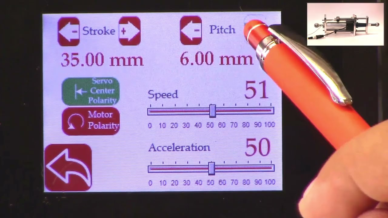
hello everyone this is arvind seshadri from Roll to roll Technologies today we're going to touch briefly about our actuator settings how do we set different parameters on the actuator on our scu5 all of our su5 controllers have the ability to connect to a variety of different actuators that are driven by stepper Motors we provide our own drivers for it if you look at our documentation you can see that from the su-5 controller we go to a motor driver through the motor communication cable and from the motor driver we go to the actuator through the actuator cable because we have the flexibility to connect a multiple different types of actuators we also provide the ability to set up some of the parameters of the actuator through our su5 controller that's what we're going to look at today and we're going to see how to set the stroke of the actuator the pitch of the actuator the speed the polarity and so on and so forth we do have our one of our actuator connected right now to the scu5 controller and that's the one right here and this is this is our standard upgrade kit actuator and this one has a front spherical eye and a rear spherical eye and then it has bearing supporting the the actuator to extend and retract and this is our LHS series with a four inch stroke this actuator also has a Servo Center sensor that is installed right here and that's actually looking at the rail that is going in and out the servo Center basically allows us to quickly Center the actuator or home the actuator to a position which makes the web guide be parallel to the other rollers within the machine we'll also go through that in another video but essentially we have our actuator connected here and then if you use our sc5 controller to move the actuator you can see that the actuator is moving back and forth and that's also seen on this bar graph right there so we'll take a look at how we're going to set some of the parameters that can be done by going into the tools icon and then power user and then actuator and this provides you with some of the settings that are currently available and this shows a pitch of 0.25 inch a stroke of 1.38 inch there's also a motor polarity setting here and then the speed and the acceleration but when we ship our controller we based on the actuator that is purchased we preset those values in the controller and ship it but if you want to change it it's pretty simple so for example if I want to change the speed I can just drag this right there and set the speed and we can also change the acceleration the speed and the acceleration can be changed independently and the pitch of the actuator is depending upon what the actuator is and that is basically one revolution of the motor how much is the actuator going to extend or attract in our case this particular actuator has a pitch of 0.25 inches and that's what it is set up there if you need to change the pitch you can just press this button and it's going to increment or decrement the pitch the units right now is shown is in inches and if you want to see those units in millimeters you can go to this screen hit the operator icon hit the display and change the units to millimeters and once you do that you can go back to the power user actuator and you can see that the actuator units are now in millimeters this is about 6.5 or 0.25 inch approximately and then the stroke is 35 millimeters and you can probably set it to the stroke on the actuator the stroke that you set is not the actual mechanical stroke that is available on the actuator this is just an electronic limit in order to avoid some of the pitfalls with existing some of the other actuators that are available where if there's issue let's say the web breaks the actuator may go back go to one side and it might keep driving because it has Reach This limit it doesn't know it has reached this limit and it keeps driving it and that might burn out the actuator to prevent that from happening in our case we actually have an electronic limit that means that if the actuator reaches its electronic limit whether the actuator whether there is a mechanical limit or not it will stop just to show you how that works I'm going to set the stroke to be some really small number let's say 30 millimeters and if I go back to the home screen and I try to jog the actuator you can see that it's going in and right now the actuator position is it's showing that it has reached it's fully retracted limit even though if you look at this actuator there's a lot of stroke remaining so if you look at here there's still a lot of room for the actuator to retract more but it stopped at this electronic limit just to prevent it from burning or destroying the motor so the electronic limit can be any limit that you set and that limit of whatever that the stroke that I showed again if I go back to the screen and to the actuator you can see that the 30 what that 30 means is that it's going to be 15 from the middle of the actuator position and on one side and then 15 on the other side and that's what the stroke means so if you are in the middle position of the actuator you can go 15 on one side and 15 on the other side that's what the stroke means in terms of setting there's also the polarity so what we can do is we can change the polarity and if you remember when I did this when I pressed the Plus it was going in a certain direction and if I do this when I press the plus it's actually extending in the previous case when I pressed the plus it was actually retracting and that's also shown here in this position when the polarity is the standard polarity the plus will increase the actuator position and that's what this is showing and the negative will decrease the actuator position so it's retracting if we reverse the polarity then it will do the opposite and again when we reverse the polarity that it clearly shows here now if we press the plus it's extending retracting and then if you do the minus it's actually extending so the polarity can be changed as I'm moving the jogging the actuator back and forth one of the things that you can notice is that the this bar graph changes color and right now it's in yellow or Amber and then if I go to another limit and now it becomes red this is more evident in the other direction so if I go all the way in the other direction this is going to be yellow and then if I go reach a certain it goes to Red this is a quick visual indication for the operator to know that the actuator is close to its extreme position if not at the extreme position if it's in red it's within 10 percent of the extreme position limit and if it is in yellow then it's between 20 percent to 30 percent of the extreme limit so we don't typically like to run the web guide in this position is that there's not enough room for correction in this direction so if there is an error in this direction and the actuator needs to move that way there's not enough room to correct for it so anyway a quick visual indication for us to see where the actuator is again if you want to see that in a bigger screen if you just click on that motor icon then you can see that the same bar graph that you saw on the home screen that's essentially the things with regard to the stroke and the pitch and the the speed and the polarity again just to reiterate there is a difference between the mechanical limits and the electronic limits the mechanical limits are the actuator cannot move anymore because it's mechanically inhibited and we never want to set that actuator or install the actuator in that scenario where the mechanical limits are reached the electronic limits are just safely limits and this allows us to stop the actuator from moving even before it reaches the mechanical limits so we typically suggest that you install the actuator move it back and forth find the Home position set the home position or this Servo Center position and then set a certain stroke and then jog all the way to one side make sure that it doesn't hit the electronical limits and jog all the way to the other side and make sure that it doesn't hit the mechanical limits and as long as it doesn't then the electronic limits are fine if in any scenario whether you're going jogging left or jogging right it hits the mechanical limits then you would have to reduce the electronic limits so we never get into that situation where the actuator might hit the mechanic that's all we need to do in terms of setting up the actuator in terms of the stroke and the pitch there are other few functionalities that are available for certain controllers for example the actuator position if it reaches the extreme position there is a way for us to set digital outputs so that not just an operator needs to look at it but the digital output can provide a signal to the PLC to alert PLC that hey the actuator has reached this limit the other option that we have this is mainly for our big actuators that are moving the unwinds and rewinds which are susceptible to damage if we reach the mechanical limit that we can add additional limit switches either mechanical limit switches or even electronic limit switches make sure that the mechanical limits are never reached and if we have that option if we have the hardware provided with your actuator then you have the ability to enable them the way to do that is to get into the tools and then the power user and then in the controller there's this limit switches icon button and then we just need to turn on the limit switches if you don't have the limit switches and you turn on the limit switches the actuator might not move just be aware of that but if you do have the limit switches and you want to enable that functionality then you can enable that functionality by turning on the limit switch so those are the basics of the actuator settings in terms of stroke pitch polarity limits and limit switches in a subsequent video we'll talk about the servo Center functionalities but in the meantime do subscribe to our Channel and we'll see you in the next video