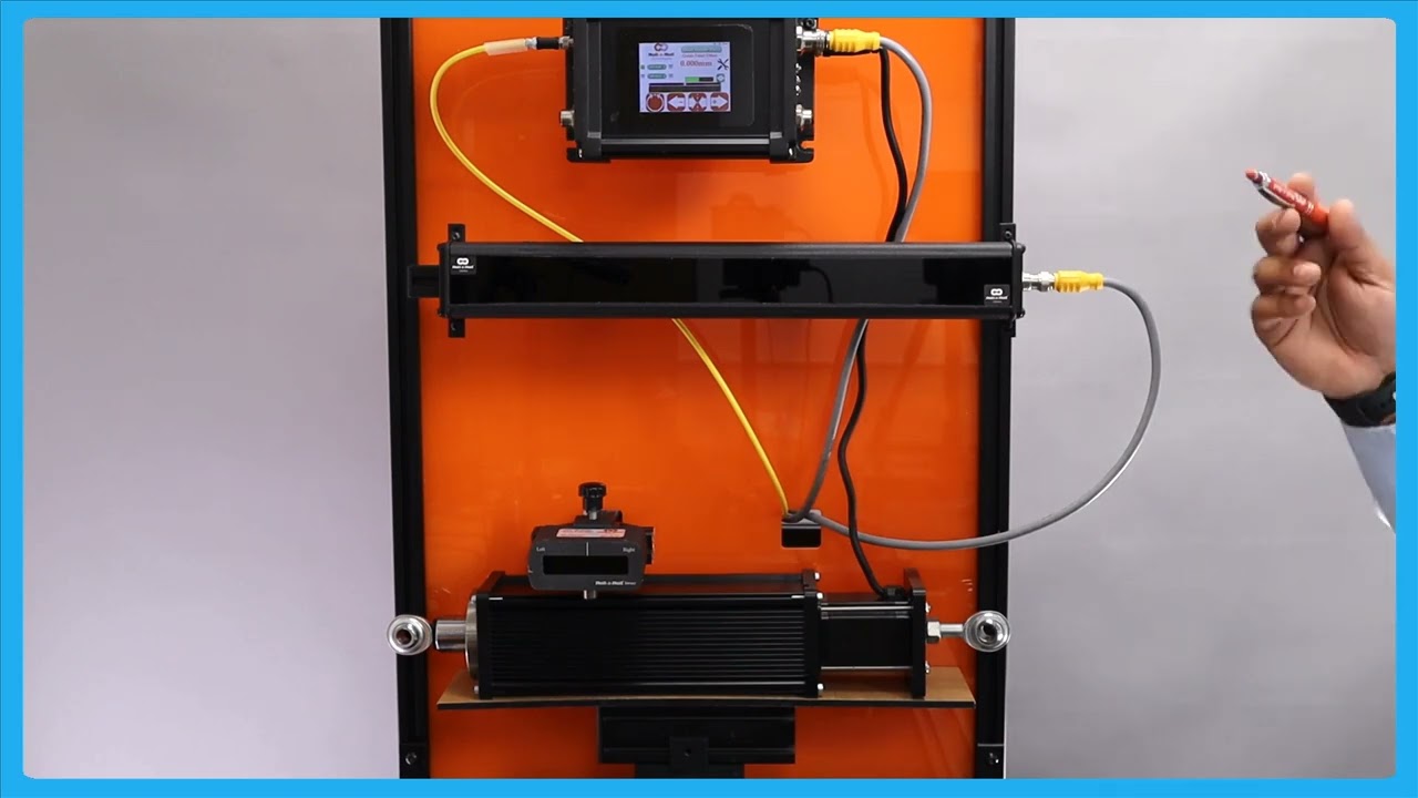
In this video, we dive into the SCU 6X controller and its capabilities. We discuss both the SCU 6X MD and SCU 6X MXD models, focusing on their use with low and high thrust actuators. You'll learn about the specifications, including current draw and thrust force, as well as the different connector and power input requirements for each model. Perfect for anyone involved in web guiding technology.
Transcript
Show full transcript (243 words)
so what we have today is our SCU 6X controller this is SCU 6X MD and we have one sensor connected to it then in the motor port we have an actuator connected to it right there seu 6X MD and there is another option SCU 6X mxd both of these options are allowing us to connect different thrust actuators for example this particular one Su 6X MD has the low thrust option where we have an actuator that can drive up to about 300 lb force of trust anything related to intermediate web guiding this will be the actuator for that this particular actuator can draw up to 4 amps of CCT when we go to a higher prust the part number is going to be a little bit different it's going to be s use 6X mxd where the X relates to the extra in that we need and that particular one can drive up to about 500 lb of thrust so a shifting stand with the total weight um of no more than about 5,000 lb can be driven with that actuator the only difference would be the connector here would be a little bit different on this side now it'll be a high thrst a high current connector and then for that particular actuator we would also need a different power in the Dual rear power input will have 7 amps up to 7 amps for that we also can do up to 48 H VC

In this episode, we delve into the functionalities of the SCU6x Controller, focusing on the manual movement of the actuator to aid in the loading and unloading of the roll. The highlight of the video is the automatic web guiding system, which ensures the web is steered to its correct position. The presenter demonstrates how the actuator responds to the positioning relative to the guide point and explains the actuator's movements and limitations based on error correction.
Transcript
Show full transcript (211 words)
okay this is about moving the actuator manually to facilitate loading and unloading the r but the real thing with our system is basically it does guide the web automatically to its desired position so just to show you that let me present the web put the web guide in automatic mode so as you remember that the gray bar in the middle is basically our G point and if we are on one side of the G point the actuators will move one way if we are the other side of the G point the actuators for to M be away and it's that's out it's stting the we and then the actuator position bar indicates what the stroke of the actuator is and obviously once a r it stroke it doesn't matter how much eror we have the accelator is not going to move in that direction but if the eror is f on that direction then the aurator is for Mo and you that in for BL so this is the automatic feature of our web guing system and right now I'm using a single edge to gu the material and it doesn't matter if I have one Edge or two edges it will do the same thing
In this video, we explore the process of center guiding using a single sensor. Unlike edge guiding, which focuses on one edge, center guiding utilizes both edges, making it highly effective for managing changes in web width. The tutorial covers setting up the sensor to detect the web's voltage, aligning the web's centerline with a guide point offset, and maintaining the center position with the actuator.
Transcript
Show full transcript (421 words)
so the next thing that we're going to look at is we showed how to do Edge guiding with a sensor now we're going to do how to do Center guiding with the sensor so I'm going to change this orientation sensor orientation so that sensor one can detect voltages of the web and that's what it it's detecting and as you remember from our previous video when we do Center gu and the GU the reference for the web is not based on one Edge actually based on the two edges so that's what is presented by this green bar so if I move the center line of that web to this green bar to this point box act and then put it an auto then when that Center Line changes position that's how we're going to guide it essentially s guide so what is the advantage of Center guiding is that when you hand weight changes you don't have to move the sensor as long as you get Point offside is the right location so for example if I put another web that's wider you can do a on the Fly Wick change with one to another web Wick and it will automatically guide and either one in a SLE L position and that's one of the biggest Advantage with a center diting solution is that when the wit changes let's say it have some variability in your Bri your web will always be presented to the center line of the machine as long as the center as long as the sensor is set up properly then you can bring it to that Center Line position with respect of the quadr or half an inch we with so in terms of Center guiding Center position is represented by the green bar and then the web guide is going to keep that Center position um I'm moving the actuator back and forth so that green bar aligns with that gray gray T point and preference as it should so that's the main difference between Edge guiding and Center Tiding again you still have that option of web break so the web braks it will stop actuating and it will start back actuating when the web is stressing and then obviously it's going to do it it's going to stop until the web reaches its B Point reference if the WID ches doesn't matter that's long red W the center line set so that's Center D with with a single sensor
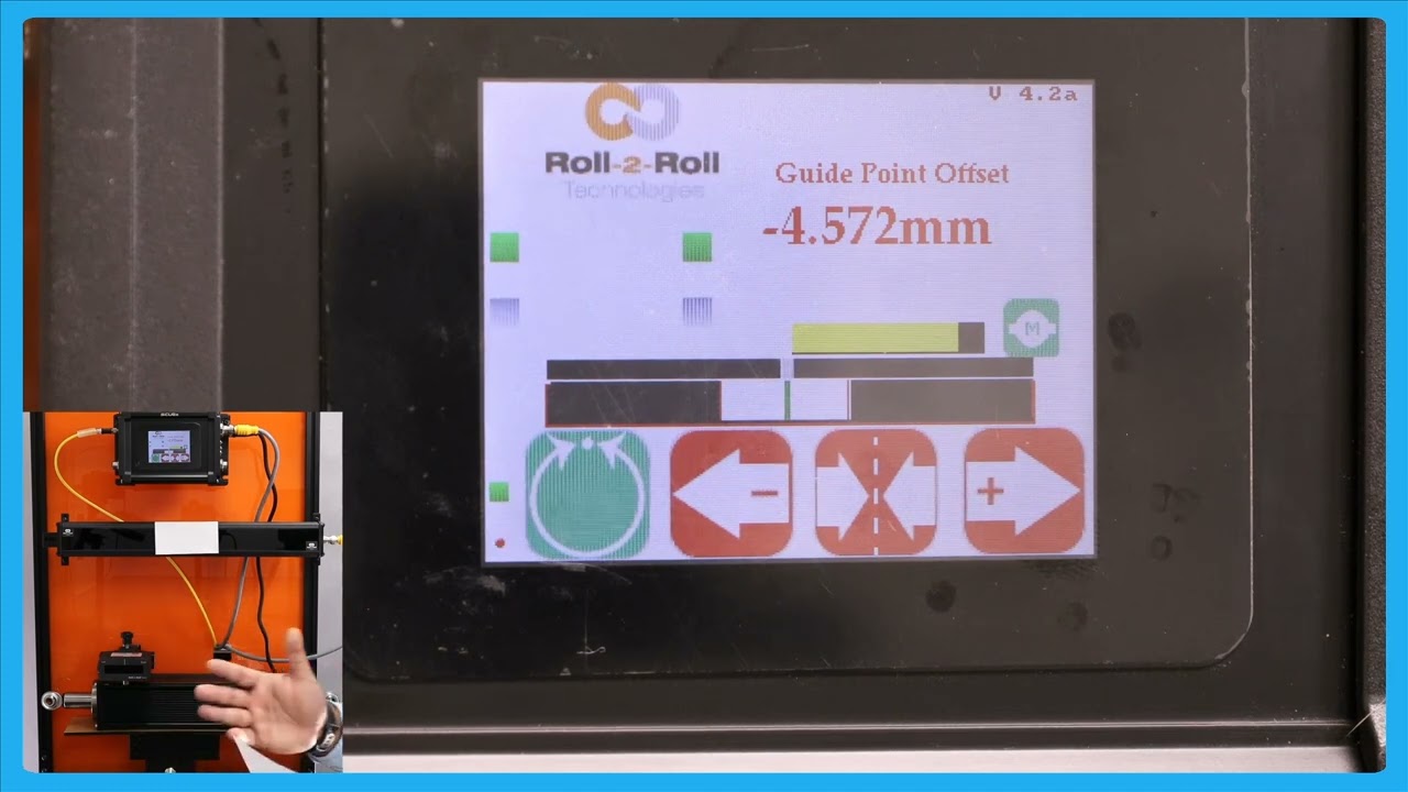
In this video, we delve into the intricacies of making fine guide point adjustments in web guiding systems, particularly during processes like lamination. Traditional methods use a micrometer screw for adjustments, but this video explains how to make precise, real-time guide point changes automatically. Learn how to adjust the guide point by increments of 0.1 millimeters, ensuring optimal alignment without stopping the web movement.
Transcript
Show full transcript (293 words)
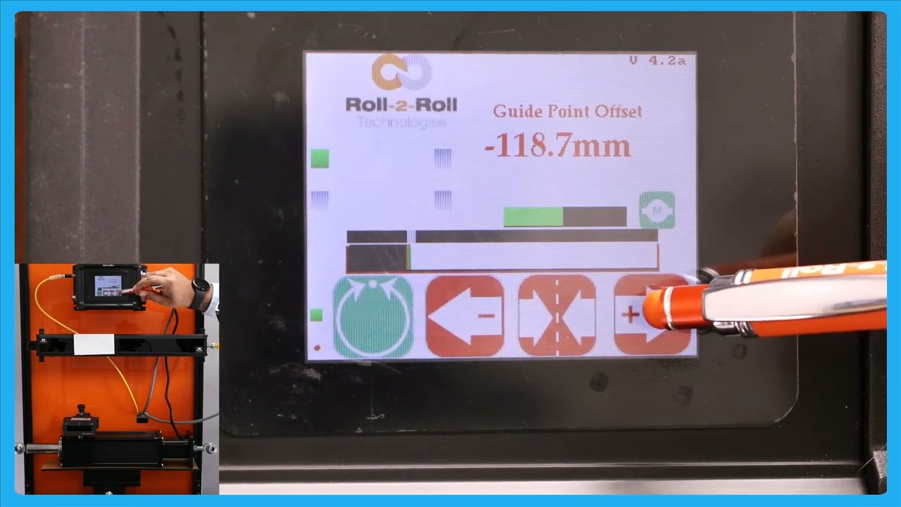
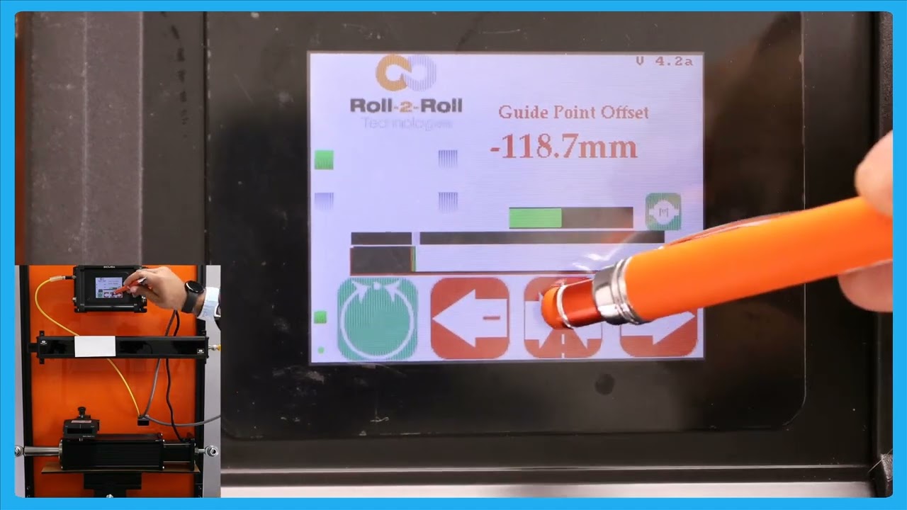
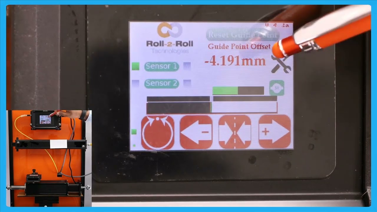
now there are situations where you are guiding the web you got it at the part but you want to make a fine adjustment and with the traditional sensors there might be something like a micrometer and an operator needs to reach in and try to adjust that screw on the micrometer to move it back and forth to do what is called as a fine day point adjustment so think of it like a lamination process you got the wind allign guiding but you want to change that gide point just a little bit you don't want to make too much of an adjustment and you want to do that while the wind is running and that is what we call as a fine G point adjustment how to do the fine gate point adjustment right now the gate Point offset isus 119 mm and if I want to change that just a little bit then I if I want to increase that I can press that increases that the web gate is not going to move until it goes away from B so just to illustrate the SP thing now it reach the limit for the dead man and it's continuing there that's our fing G point adjustment so this allows you to be able to Mike uh make very fine adjustments to the guide point again the plus arrow allows you to increase that g point and minus Arrow allows you you would decrease that g Point that's what is called a fine G point adjustment and this adjustment can be done only when we are in automatic mode and then each press of that will take1 mm I think that's what it looks like1 mimet to move the gate BL
This episode provides a detailed explanation on how to reset the guide point offset to zero in automatic mode using the servo center button. The process is highlighted with caution due to its powerful impact on the guide point and web position, emphasizing that only knowledgeable users should perform this operation. Viewers learn how pressing the servo center button prompts a confirmation to reset the guide point, and accepting it results in moving the actuator to correct the web position to the new guide point reference.
Transcript
Show full transcript (234 words)
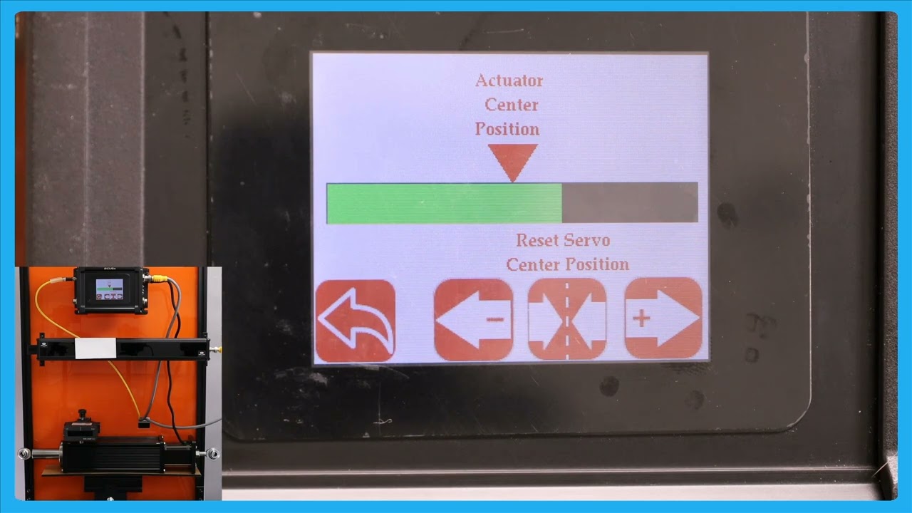
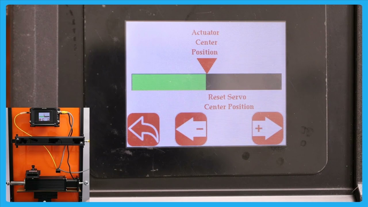
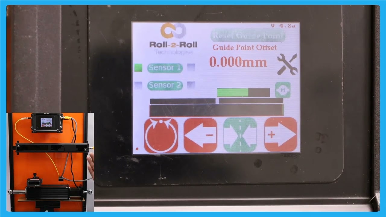
okay one other feature in terms of resetting the G Point how that we have is there are some occasions where you want to reset it to zero and this has to be done with extreme care and only people who know what they're doing should be able to do this and that's because this is very powerful and changes the G Point immediately so there might be some loation where you want to absolutely reset pick 8. to0 the best way for us to do that is while it is in a Ned did you press the servo center button it's going to show you that hey you want to reset the G point to zero do you want to accept it obviously if I accept it the web isit a different location it's going to go all the way to one side the actuator is going to go all the way one side because it's trying to correct for the web position again when you're in automatic mode if you press this Servo center button then it would allow you to reset the T point if I press accept the T point is going to be in the middle now basicly the actuator is newly because it's trying to bring the we toward its um to the gr Point reference that's the way in which you could reset the G point to see
In this video, we revisit the concept of the guide point offset and how to reset the guide point using the SCU6x Controller. This technique is particularly useful when working with wide sensors and handling the web at different positions. The video walks through the steps of resetting the guide point, both in automatic and manual modes, ensuring precise guidance of the web. By following these instructions, you can maintain the correct positioning and handling of your web material, helping to enhance operational efficiency and accuracy.
Transcript
Show full transcript (179 words)
okay in our previous video we looked at the guide point offset basically how to reset the G Point again that is useful when you have a white sensor and you uh present the web like different locations so just to go over that one more time here I've got a white sensor here and the web is positioned at some point I'm going to go in and reset great Point except up there and if I put the we p in automatic it's going to stay in that position and if I need to change that date point to a new location when it's in manual and we can still do that the web isit this new location and I'm going to do the reset cway accept and when I put it in Auto in SC the actuator is staying in position because the web is at the point location and if I move the web to one side part the other it's little stop it's going to die with respect to that and that's the re cway
In this episode, we explain the functionality of an enhanced operator interface that provides a larger view of the actuator position. This feature is particularly useful when operators are working at a distance from the controller, allowing them to make precise adjustments without the actuator reaching its limit. The video demonstrates how the web guide operates in automatic mode and explains the benefits of being able to view the actuator bar from different parts of the machine.
Transcript
Show full transcript (211 words)
one of the reasons why we have this icon where the operators can see a the view of the actuator position is those scenarios where an operator farther away from our controller and they want to make some subsequent adjustments to the position or essentially the date Point using the the mode operator interface but they want to make sure that adjusting the G point doesn't make the actuator to reach its limit that's all of the reasons why we have that right now the web guate is in automatic mode and the web is staying there it's not moving but if I move the web guate you can see that you can the actuator bar changes if this is just a bigger view of what we had in the home screen and the reason why is uh a bigger view is allowing The Operators to see this interface from a longer distance while they're making adjustments to other parts of the machine so that if the actu reaches its limit it's pretty evident and they can make adjustments to the other part of the machine so that it doesn't guide doesn't lose its stroke during guy this button you can reach it either in automatic mode or in manual mode
In this video, we explore an important feature of the SCU6x Controller related to the servo center position. We discuss a scenario where operators are not permitted to change the servo center position and how the controller can be configured to lock this setting. By clicking on the motor icon, operators will only be able to see the jog left and jog button options, while the reset servo center button will be hidden.
Transcript
Show full transcript (135 words)
so one other option that we have is that if if the operators are not allowed to change the servo Center position then in that scenario the controller can be locked in such a way that the operator cannot change that simple Center position then if you click on this motor icon now it'll only show you the jog length and the jog button and it won't show you that reset Servo center button so the operators could just view the actuator position and not be able to reset the C Center position so that's the difference between having n enable and disable this is about moving the actuator manually to facilitate loading and unloading the RO but the real thing with our system is basically it does guide the we automatically to its Desir
In this episode, we'll explore the functionalities of the SCU6x controller, focusing on the different operations of jog buttons, and the servo center feature. We'll explain how the servo center button positions the web guide in neutral and how this differs from the momentary jog buttons. The video also covers indicator states for the servo center operation, including how it transitions from green to red. Future videos will detail more about the methods for servo centering, including using electronic limits and physical proximity sensors.
Transcript
Show full transcript (341 words)
now if you want to put the web guide in Servo Center basically means different things for different types of web gues but essentially putting the web guide in a newos so that it has enough stroke to go on either side um of the servo Center position then you can press this button and this button uh it's a single press button and when you press that it will bring the web guide or the actuator to its home position or what we call as the zero position so one difference between the jog buttons and the servo Center buttons or that these jot buttons or what we call as momentary buttons that means that you need to keep pressing there for the actuator to keep jogging as soon as you let go the actuator is going to stop jogging in that case both of them are like that um Ciro Center is more like a push button and it it will actually tell you the Stak in which it is there for example if I johned it and then if I put it to server Center this is in the servo Centric state so it's going to be green and until the servo center operation is done it will stay green and once the operate operation is done it will turn back to Red so there's no need for us to keep pressing that button it's a one time push button C so click just to give you this again when you press the servo Center it's going to uh bring the actuator to its home position once the operation is done once it reaches the home position it's will turn back to um reding there are different ways in which we could do the servo centering operation which will be handled in a future video essentially depending upon whether we are just using an electronic limit or if we're using a physical proximity sensor to do that so those are for the jog left Jog and turbo Center
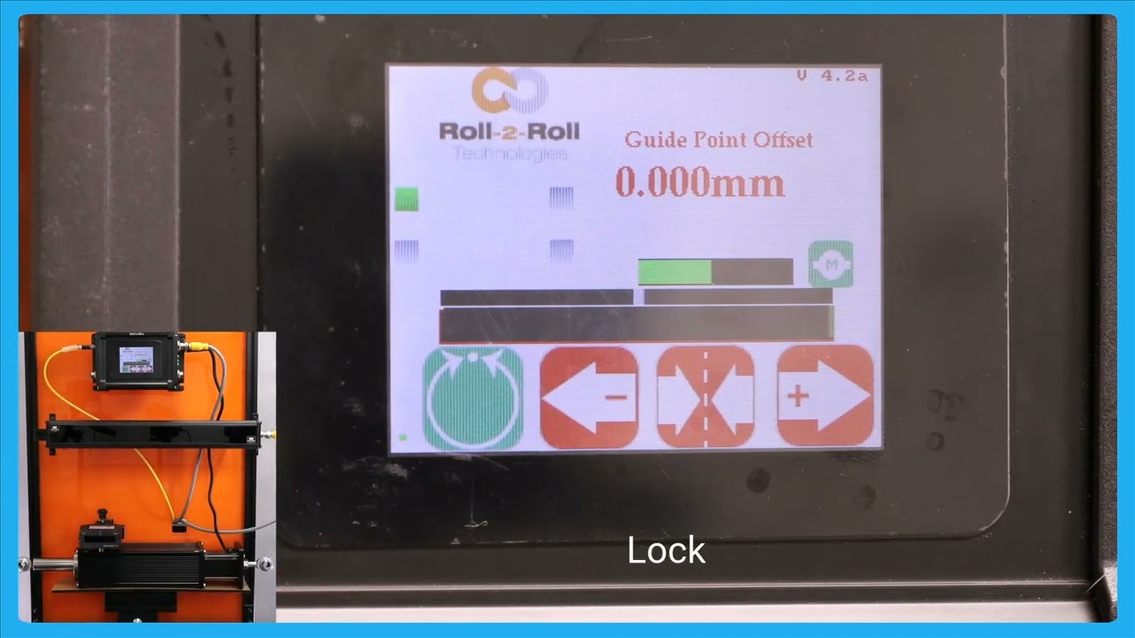
In this video, we introduce and explain the automatic web detect signal feature of the SCU6x Controller. This functionality ensures that the actuator stops moving when the web breaks, even in automatic mode. The video illustrates how the actuator guides the web back and forth and demonstrates the lock on lost edge feature, which holds the actuator's position if no web is detected. This feature is crucial for preventing disruptions in operations when re-threading the web.
Transcript
Show full transcript (199 words)
so one other feature that we have is that we have an automatic web detect signal in a previous video we talked about this which is that web detect signal we can use that information to stop the actuator for movie even while it's in automatic mode if the we breaks so just illustrate that I'm going to show that and stting the web Maring toward and you can see that actuator position but if the web breaks and there's no web in front of it then the actuator stay stays put and this is what we call as lock on Lost Edge essentially a functionality that ensures that the actuator doesn't get cocked to one side or the other if there is no web in the field of view of the centor and as soon as the web comes back it's going to start dating it when there is a web break it's going to start and hold it position and this is essentially for detecting the uh web Brak and then making sure to stop the actuator in its current position so that it doesn't disrup the the operation once the direct web is started back in