Unwind Guiding
Feed Perfect Alignment from Imperfect Rolls. Precision Shifting Stands.
In roll-to-roll processing, the material entering the machine must be perfectly aligned, even if the source roll is telescoped or loaded off-center. An Unwind Guide (or Shifting Stand) physically moves the entire heavy unwind roll left or right to ensure the web enters the process at the exact correct cross-machine location. Unlike intermediate guides that bend the web, this system shifts the bulk mass of the roll, requiring high-thrust actuation and specific mechanical geometry to maintain stability.
The Challenge: Heavy Loads and Telescoped Rolls
Unwind guiding faces unique challenges compared to standard web guiding because it deals with the highest mass in the system:
- Variable Roll Quality: Incoming rolls are rarely perfect. They may be telescoped (uneven edges) or wound with camber. If these errors aren't corrected immediately at the unwind, they propagate through the entire machine, causing wrinkles and registration errors downstream.
- Massive Inertia: The system must move the entire weight of the roll (often thousands of pounds) plus the stand structure. Legacy systems relied on hydraulic cylinders to generate this force. These systems are messy, prone to leaks that contaminate products, and require costly maintenance of filters and seals.
- Operator Loading Errors: If an operator loads a new roll slightly off-center, the web guide must immediately correct for this steady-state error before the web enters the machine.
The Cost of Inaction: What Legacy Systems Are Costing You
Every month you continue operating with legacy hydraulic unwind systems, you're accumulating hidden costs:
- Direct Costs: Hydraulic fluid replacement, filter maintenance, seal repairs, and the downtime required for each service event.
- Hidden Costs: Operators repositioning narrow sensors for every width change, extended changeovers, and the labor time that never shows up in downtime reports.
- Risk Costs: A single hydraulic leak can contaminate an entire roll of product. In food, pharmaceutical, or medical applications, this means scrapped material and potential compliance violations.
- Opportunity Costs: Limited to edge-only guiding? Many slitter rewinder applications require line guiding on printed materials, but traditional systems cannot switch between modes without hardware changes.
Plants using legacy hydraulic systems typically spend 10-20 hours annually on unwind guide maintenance alone—time that could be running production.
The Solution: Roll-2-Roll® Actuators
We replace leak-prone hydraulics with clean, high-precision electromechanical actuators that provide the thrust needed to move heavy stands without the mess.
The Roll-2-Roll Advantage:
- High Thrust, Zero Fluids: Our actuators utilize stepper or servo motors coupled with ball screws or planetary roller screws to move loads up to 30,000 lbs (with low-friction linear bearings). This eliminates the risk of oil spills ruining your production.
- Stiff Control Loop: Large masses are prone to mechanical resonance. Roll-2-Roll® Actuators are designed with high structural stiffness to ensure the natural frequency of the stand is well above the control frequency (typically 25-50 Hz), preventing oscillation during rapid corrections.
- Wide-Area Sensing: Our wide-band sensors allow for significant web wander without the sensor losing the edge, accommodating poorly wound rolls that would cause traditional narrow sensors to fault out.
Engineering Guide: The "Fixed Sensor" Rule
The physics of Unwind Guiding are the exact opposite of Rewind Chasing. To ensure stability, you must follow these specific installation rules:
- The Sensor MUST Be Fixed: Unlike a rewind system where the sensor moves, in an unwind application, the sensor must be fixed to the machine frame (floor).
- The Logic: You are trying to guide the web to a specific target in the machine. Therefore, the sensor acts as that target. The controller moves the shifting stand until the web aligns with the fixed sensor.
- Common Mistake: If you mount the sensor on the moving stand, the sensor moves with the error, and the system cannot detect the misalignment relative to the machine.
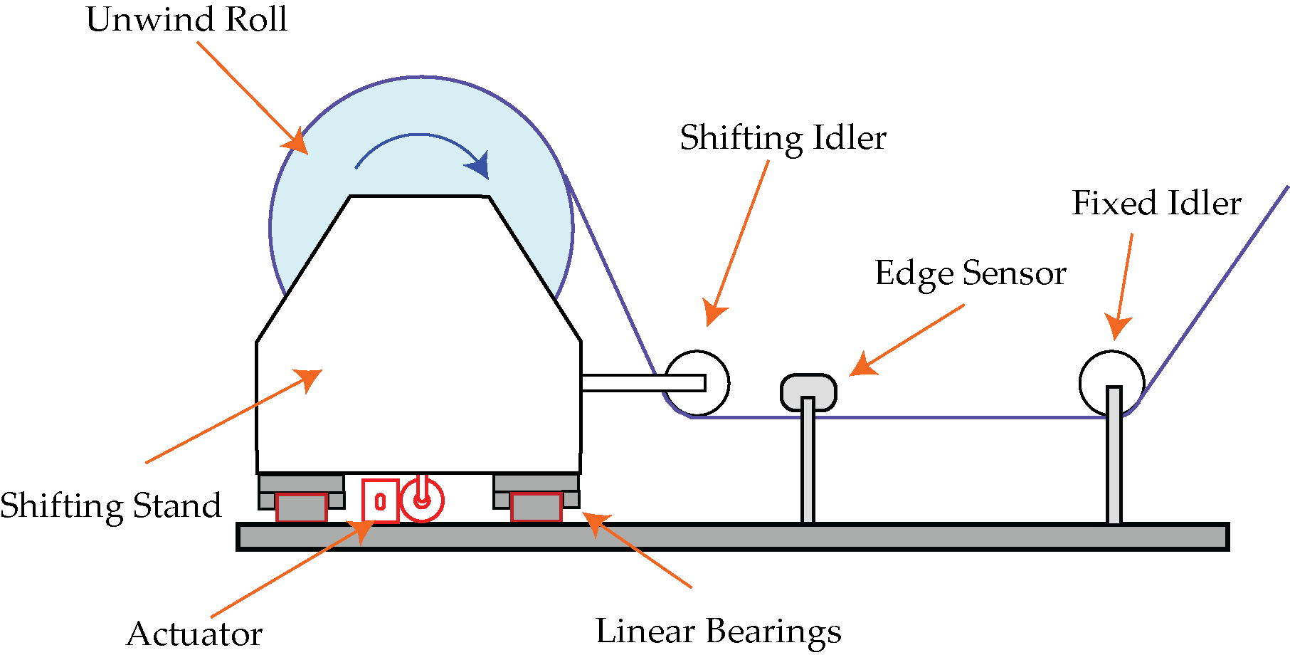
- The "Shifting Idler" Requirement: You must install at least one idler roller that moves with the unwind stand (a shifting idler) before the web reaches the fixed sensor.
- Why? As the roll diameter decreases from full to core, the web plane changes. If the web went directly from the changing roll to a fixed sensor, the pass line angle would constantly change, affecting sensor accuracy.
- The Geometry: The shifting idler creates a consistent web plane relative to the roll. The sensor is placed immediately downstream of this shifting idler.
- Actuator Sizing: Sizing an unwind actuator requires calculating more than just the load mass; it is critically dependent on friction.
- Breakaway Force: The actuator must provide enough force to overcome the static friction of the linear bearings.
- Recommendation: Use low-friction linear rail bearings (coefficient ~0.01) rather than sliding shafts (coefficient ~0.25). High-friction bearings require significantly larger actuators to achieve the same response time.
- Alignment: Precise alignment between multiple linear rails is critical to prevent binding. Misalignment artificially increases friction, requiring additional thrust to move the stand.
Key Advantage: Dual-Mode Sensing for Slitter Rewinders
Traditional unwind systems face a limitation: they can only guide off the web edge. But many converting operations, especially slitter rewinders, need to guide off a printed line or registration mark for certain products.
With Roll-2-Roll Technologies wide-aperture sensors (up to 960mm sensing range), you gain capabilities that legacy systems simply cannot match:
- Edge AND Line Guiding: A single ODC 960 sensor can switch between edge guiding and line/contrast guiding without hardware changes. Process opaque materials using edge detection, then switch to printed film using line detection—all from the same sensor.
- No Sensor Repositioning: Wide sensing range accommodates multiple web widths and multiple web paths without moving the sensor. Reduce changeover time and eliminate operator errors.
- Multiple Web Paths: Some operations run different materials through different web paths on the same machine. Wide sensors handle both configurations without reconfiguration.
For Slitter Rewinder Applications: This dual-mode capability is particularly valuable. You can guide off the edge for standard materials, then seamlessly switch to guiding off a printed line for laminated or pre-printed substrates—all without changing sensors or stopping the line.
System Configurations (Select Your Kit)
Unwind Guiding Kit
Best for: Loads less than 3000 lb and for replacing leaking hydraulic cylinders on existing shifting stands.
- Actuator: Roll-2-Roll® Actuator Electromechanical Stepper.
- Sensor: Wide Roll-2-Roll® Sensor (Fixed to machine frame) allow for web width change without sensor repositioning.
- Controller: Roll-2-Roll® Controller such as SCU6x MxD with built-in motor driver for high thrust actuator.
- Benefit: Eliminates hydraulic fluid, filters, and valve balancing.
Heavy-Duty Unwind System
Best for: Metals, heavy paper, and large diameter film rolls.
- Actuator: High-Thrust Ball Screw or Planetary Roller Screw option.
- Sensor: Wide Roll-2-Roll® Sensor (Fixed to machine frame) allow for web width change without sensor repositioning.
- Controller: Integrated drive with regenerative braking compensation to handle the inertia of large shifting masses.
Technical Specifications
| Specification | Value |
|---|---|
| Load Capacity | Up to 30,000 lbs (13,600 kg) with low-friction bearings |
| Thrust Range | 50 lbf (222 N) to 1,500 lbf (6,670 N) |
| Stroke Length | 1 in (25 mm) to 12 in (300 mm) |
| Maximum Speed | Up to 2 in/sec (51 mm/sec) |
| Sensor Range | 48 mm to 960 mm (ODC Family) |
| Control Frequency | 25-50 Hz typical |
| Industrial Protocols | EtherNet/IP, PROFINET, EtherCAT, Modbus/TCP |
| Voltage Options | 24 VDC or 48 VDC |