Edge Guiding Systems
Precision Web Alignment. No Recalibration. No Mechanical Adjustments.
Edge guiding is the process of automatically positioning a flexible web (material) by tracking one of its edges as it moves through a machine. Unlike traditional systems that require operators to physically move sensors whenever the web width changes, Roll-2-Roll Technologies uses wide sensors. This allows operators to adjust the "guide point" electronically via a touchscreen, eliminating mechanical downtime and operator error. Our technology is material agnostic, meaning it detects clear film, opaque materials, and porous nonwovens without requiring sensor recalibration.
The Challenge: The "Old Way" of Edge Guiding
For decades, single-edge guiding has been the standard for web alignment. However, conventional systems introduce significant downtime and risk during product changeovers:
- Manual Sensor Repositioning: When the web width changes, the sensor must be physically moved to the new edge location. This manual adjustment is prone to operator error, leading to misalignment and waste.
- The "Blind" Spot: Narrow sensors (fork-style) have a limited viewing range. If the web wanders outside this small window, the system loses the web entirely, causing machine stops or errors.
- Material Sensitivity: Traditional ultrasonic or infrared sensors struggle with changes in material opacity or porosity (e.g., clear films or nonwovens), often requiring recalibration or entirely different sensors for different jobs.
- Temperature Drift: Conventional sensors are affected by ambient temperature changes, degrading accuracy throughout shifts.
The Solution: The Roll-2-Roll "Simplicity" Way
We utilize advanced Light Scattering Technology and wide-area sensing to solve the fundamental flaws of legacy edge guides.
Why Roll-2-Roll Edge Guiding is Different
- Electronic Guide Point Adjustment: Instead of climbing into the machine to move a sensor, operators simply adjust the "guide point" on the controller touchscreen. The sensor stays fixed, but the system tracks the new edge position mathematically. This reduces operator safety concerns, and any possible error for manual sensor repositioning.
- One Sensor, Any Material: Our sensors act like a 1-dimensional camera. Whether you are running battery electrode foil, clear optical film, or porous nonwovens, the sensor detects the edge without calibration.
- Wider Sensing Window: With sensing windows ranging from 48mm to 960mm, our sensors capture significant web width variations without needing mechanical chasing or positioners.
- Temperature Immune: Fiber-optic technology is unaffected by ambient temperature changes, maintaining accuracy throughout shifts.
- No Setup: No setup, no specialist required.
Roll-2-Roll vs. Legacy Systems
| Feature | Legacy Systems | Roll-2-Roll Technologies |
|---|---|---|
| Width Changeovers | Manual sensor movement required | Instant electronic adjustment |
| Material Changes | Recalibration often required | No calibration needed |
| Porous/Mesh Webs | Often fails or requires speciality sensors | Works natively (Material Agnostic) |
| Calibration Time | Minutes (removing and fully covering the sensor) | None (No-setup) |
| Temperature Stability | Affected by drift | Immune to temperature changes |
| Sensing Window | Narrow (fork-style) | Wide aperture (48-960mm) |
Material Compatibility: One Sensor for Every Web
Traditional edge sensors force difficult tradeoffs: ultrasonic sensors struggle with porous nonwovens, infrared sensors cannot reliably detect clear films, and changing materials means recalibrating—or replacing—your sensor. Roll-2-Roll fiber-optic sensors eliminate these compromises.
Works on Any Material Without Adjustment
| Material Type | Traditional Sensors | Roll-2-Roll® Sensors |
|---|---|---|
| Clear films | Difficult - requires ultrasonic sensors | Detects with IR reflection |
| Opaque substrates | Works | Works |
| Metallic foils | Reflections cause errors | No calibration needed |
| Porous nonwovens | Ultrasonic fails and Infrared is less accurate | Works identically |
| Mesh materials | Challenging | Detects edges reliably |
Handle Width Variations Instantly
With more converters adapting to short production runs, frequent width changes are the new normal. Traditional systems require manual sensor repositioning (introduces operator errors), automated sensor movement (mechanical wear and failure points), and changeover time for each width adjustment.
The Roll-2-Roll Approach: Our sensors provide sensing ranges up to 960 mm (38 in), allowing up to 38 inches of web width variation without moving the sensors. Set it once, and the sensor adapts to any width instantly—no lost time, no operator errors, no mechanical failures.
How It Works
An edge guiding system consists of four essential components working in a closed loop:
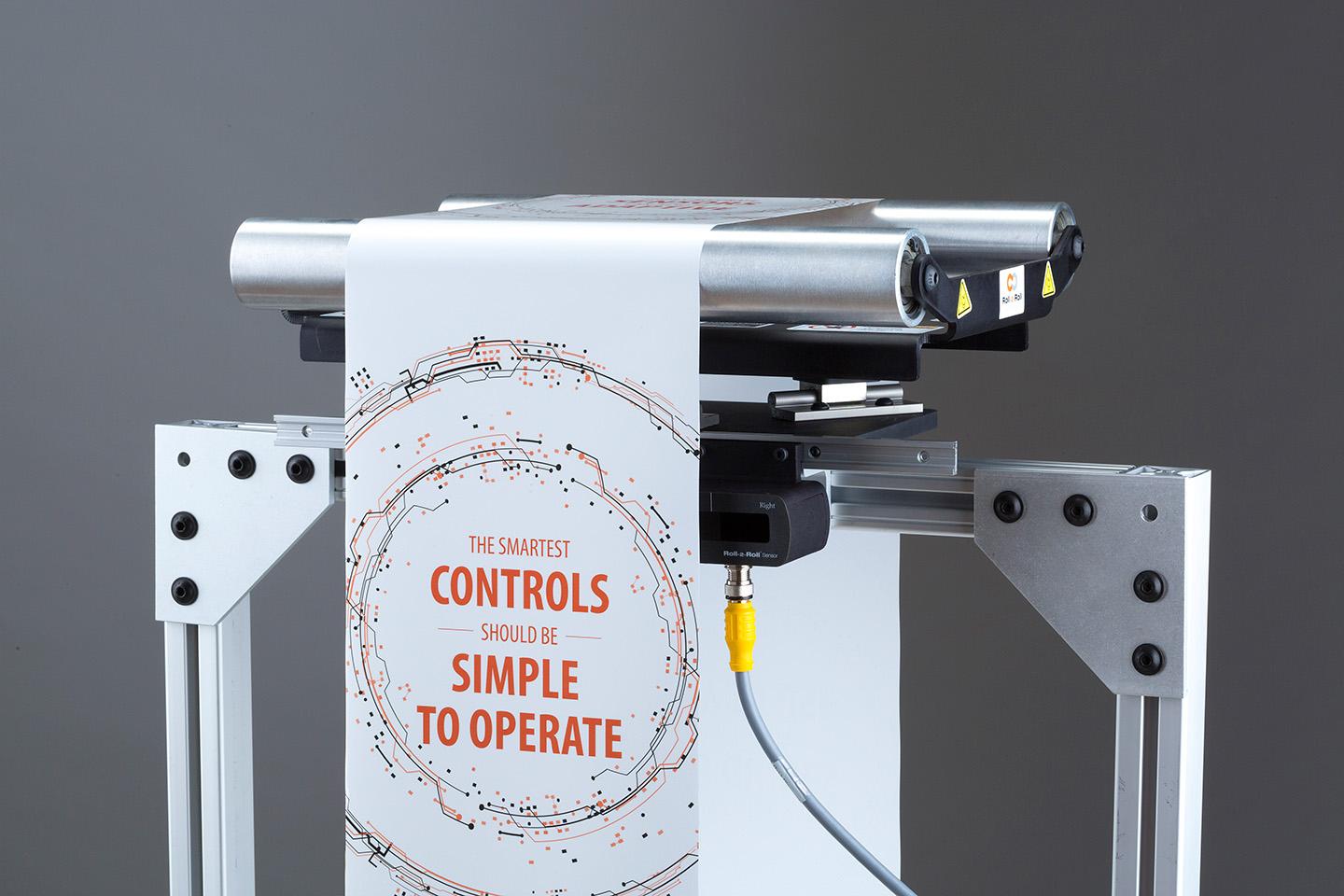
- The Sensor: Detects the lateral position of the web edge. We use Roll-2-Roll® Sensors (fiber-optic sensors) that are immune to environmental changes and work on any material.
- The Controller: The "brain" that compares the actual position to the target "guide point" and computes the necessary correction. The Roll-2-Roll® Controller SCU5 or SCU6x features a touchscreen for electronic guide point adjustment.
- The Actuator: The "muscle" that provides the thrust to move the mechanical structure. Available in various sizes from narrow web to heavy-duty unwind stands.
- The Guide Mechanism: The structure (such as a Displacement Guide or Steering Guide) that physically moves the web based on the Normal Entry Rule: A web approaching a roller will align itself perpendicular to the axis of rotation.
Engineering Note: For optimal performance, the sensor should be installed as close as possible to the exit roller of the guide span.
System Configurations
Intermediate Guide (Displacement Guide)
Best for: High-accuracy alignment inside the machine (e.g., before coating, printing, or laminating).
| Component | Model | Role |
|---|---|---|
| Mechanism | Offset Pivot Guide (OPG) | Imparts minimal stress on the web |
| Sensor | Roll-2-Roll® Sensors | Fixed position, electronic guide point |
| Controller | SCU6x with Touchscreen | Digital control, No-setup |
Applications: Coating stations, print registration, laminating nips, slitter entry
Terminal Guide Kit (Unwind/Rewind)
Best for: Managing master rolls at the entry or exit of the line.
- Unwind Configuration: Guides the web into the machine by moving the unwind stand laterally.
- Rewind Configuration: "Chases" the web to ensure a straight wound roll.
| Component | Model | Role |
|---|---|---|
| Actuator | Heavy-duty electromechanical | Moves stands up to 6,700 lbs |
| Sensor | Roll-2-Roll® Sensors | Tracks edge at unwind/rewind |
| Controller | SCU6x | Coordinates guide and chase modes |
Applications: Unwind stands, rewind stations, turret winders
Technical Specifications (Roll-2-Roll® Sensors)
Engineered for simple integration and robust performance.
| Parameter | Specification | Note |
|---|---|---|
| Sensing Range | 48 mm to 960 mm | Covers wide web variations |
| Resolution | 0.0635 mm | High precision edge detection |
| Linearity | ± 0.25 mm | Consistent across full range |
| Update Rate | 50 Hz and upto 1000 Hz | Fast response for high speeds |
| Supply Voltage | 24 VDC | Industry standard |
Industries Using Edge Guiding
- Battery Manufacturing — Electrode foil alignment for Li-ion cells
- Converting & Packaging — Film and foil alignment in slitting, laminating, rewinding
- Nonwovens & Hygiene — Diaper line web tracking on spunbond/meltblown
- Label & Tag — Pressure-sensitive label web guiding
- Flexible Packaging — Pouch and stand-up bag film alignment
- Specialty Films — Optical films, barrier films, release liners
- Metals — Copper and aluminum foil processing
ROI & Results
Reduce Waste, Improve Safety. By eliminating the need for operators to reach into machines to adjust sensors, you improve plant safety. By eliminating calibration, you reduce setup time from hours to minutes.
| Metric | Result |
|---|---|
| Material Waste Reduction* | 15-25% (typical) |
| Typical Payback Period | < 6 months (many installations) |
| Setup Time | Minutes, not hours |
| Recalibration | Zero |
*Results vary by application. Figures represent typical customer-reported outcomes.
Trusted By: Industry leaders including multi-national tape manufacturing company, medical products company, Li-Ion battery manufacturing company and diaper and adult incontinence manufacturing company.
Related Solutions
- Center Guiding — Guide by detecting both edges simultaneously
- Width Measurement — Monitor web width in real-time
- Line/Contrast Guiding — Guide using printed lines or contrast features
- Retrofit / Upgrade — Replace legacy web guide systems