Rewind/Winder Chasing Systems
Perfect Rolls. Dynamic Tracking. The "Moving Sensor" Logic.
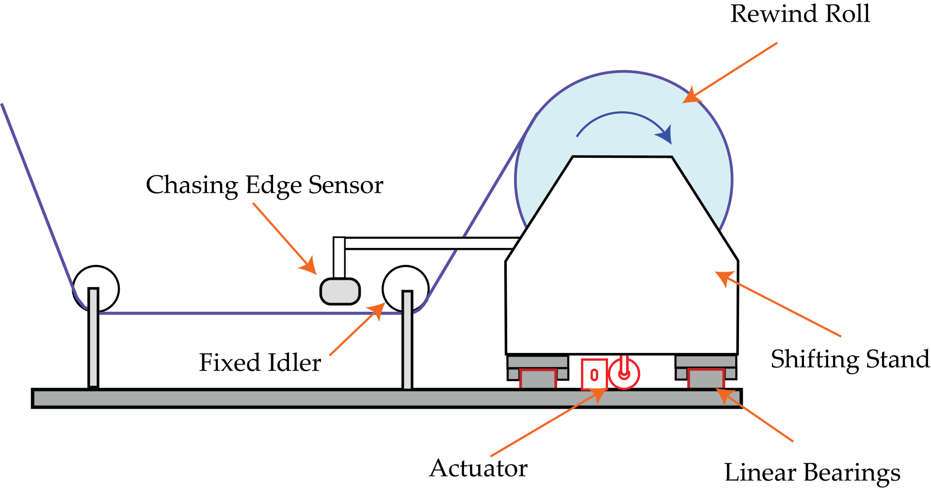
In most parts of a machine, you move the web to match the machine. In rewinding, you must do the opposite: move the machine to match the web. If a web arrives at the winder with a slight wander, holding the winder stationary will result in a "telescoped" or uneven roll edge. To fix this, the entire rewind stand must physically move back and forth to catch the incoming web. This is called "Chasing." The sensor is mounted directly to the moving stand, allowing it to lock onto the web edge and force the heavy roll to follow the web's every movement, ensuring a perfectly straight-sided finished product.
The Challenge: It's Not "Guiding," It's Physics
Rewind chasing presents unique challenges that standard web guides do not face:
- The "Moving Target" Logic: Unlike an unwind or intermediate guide where the sensor is fixed to the floor, a rewind sensor must move with the stand. If the sensor were fixed to the floor, the system would lose the relative position between the web and the roll, making accurate winding impossible.
- Variable Mass Dynamics: A rewind application is physically demanding because the load changes constantly. You start with an empty core (light) and end with a full roll (heavy). The actuator must be sized to handle the maximum roll weight (often thousands of pounds) while maintaining the agility to make small, fast corrections.
- Hydraulic Headaches: Historically, moving these massive stands required hydraulic cylinders. These introduce oil leaks that contaminate products, require filter/seal maintenance, and suffer from "valve balancing" issues where extension and retraction speeds differ.
The Solution: Roll-2-Roll Technologies Electromechanical Chasing
We replace messy hydraulics and complex linkage systems with high-thrust, maintenance-free electromechanical precision.
The Roll-2-Roll Technologies "Heavy-Duty" Advantage
- High-Thrust, Clean Operation: Our electromechanical actuators can move loads up to 30,000 lbs (with low-friction bearings) without a single drop of hydraulic fluid. This eliminates the risk of product contamination and the noise of hydraulic pumps.
- Smart "Chasing" Logic: The Roll-2-Roll® Controller is pre-programmed with specific Rewind logic. It processes the feedback from the moving sensor to keep the relative distance between the web edge and the roll face constant, effectively "freezing" the web position relative to the roll.
- Stiff Control Loop: By using stiff, zero-backlash actuators, we ensure the heavy stand reacts immediately to sensor signals, avoiding the "lag" that causes telescoping on the outer layers of the roll.
Verified Specifications
| Specification | Value |
|---|---|
| Maximum Thrust | 50–1,500 lbf (222–6,670 N) |
| Load Capacity | Up to 30,000 lbs with low-friction bearings |
| Stroke Length | 1–12 in (25–300 mm) |
| Maximum Speed | Up to 2 in/sec (51 mm/sec) |
| Sensor Ranges | 48–960 mm (1.9–37.8 in) |
| Controller Frequency | 25–50 Hz typical |
| Industrial Protocols | EtherNet/IP, PROFINET, EtherCAT, Modbus/TCP |
Advanced Capability: Dual-Sensor Bidirectional Operation
For coating applications that run forward and backward: The SCU6x and SCU5 controllers can process two sensors simultaneously with independent enable/disable control. This opens up specialized configurations:
- Sensor 1: Mounted on the rewind moving frame—active during forward winding
- Sensor 2: Mounted on the fixed machine frame—active during reverse (unwind) direction
This dual-sensor approach is ideal for coating machines that reverse direction between passes. Instead of repositioning a single sensor, operators simply switch which sensor is active via the controller interface or PLC command.
Benefits of Dual-Sensor Configuration
- No sensor repositioning between forward and reverse operations
- Instant direction changes—switch active sensor with a single command
- Reduced changeover time on bidirectional coating lines
- Simplified machine design—no motorized sensor positioners needed
Engineering Guide: The "Moving Sensor" Rule
The most common failure in rewind designs is improper sensor placement. Follow these rules to ensure stability.
The Mounting Rule
- The Sensor MUST Move. For rewind applications, the sensor must be mechanically attached to the shifting rewind stand. As the actuator moves the stand, the sensor must move with it.
- Why? The control loop is trying to keep the sensor output at "zero." By moving the sensor with the roll, the system naturally drives the roll until the sensor aligns with the web edge.
The "Fixed Idler" Rule
The sensor should look at the web while it is wrapped over a Fixed Idler (attached to the floor/frame) immediately upstream of the shifting stand.
- Placement: Install the sensor as close as possible to this last fixed idler.
- Stability: The arm holding the sensor must be structurally stiff. If the sensor arm wobbles as the heavy stand shifts, it induces "false error" and causes the stand to oscillate.
Actuator Sizing: Breakaway Force
Sizing a rewind actuator isn't just about weight; it's about friction.
- Formula: The actuator must overcome the Breakaway Force (Static Friction) of the linear bearings under full load.
- Recommendation: Use low-friction linear rail bearings (coefficient ~0.01) rather than sliding shafts (coefficient ~0.25) to reduce the actuator size required.
System Configurations (Select Your Kit)
Standard Rewind Chasing Kit
Best for: Converting lines, slitters, and laminators rewinding rolls up to 10,000 lbs.
- Sensor: ODC 192 or ODC 288 (mounted on the moving stand)—wide aperture accommodates multiple web widths without repositioning
- Actuator: BLA Series electromechanical actuator (replaces hydraulic cylinder)
- Controller: SCU6x with integrated motor driver—compact solution for most converting lines
Heavy-Duty Retrofit Kit
Best for: Metals, heavy paper, and large diameter film rolls exceeding 10,000 lbs.
- Sensor: ODC 480 or ODC 768 for wider webs
- Actuator: RLA Series ball screw actuator—thrust up to 1,500 lbf (6,670 N)
- Controller: SCU6x with diameter-based gain scheduling via EtherNet/IP or PROFINET (adjusting response as the roll gets heavier)
Cost of Inaction: What Staying Put Is Costing You
Every week you continue operating with legacy hydraulic systems or undersized guides, you're accumulating hidden losses:
Hidden Costs (Untracked but Real)
- Hydraulic maintenance labor: Typical plants report 10–20 hours annually on unwind/rewind guide maintenance alone—filter changes, seal replacements, valve adjustments
- Sensor repositioning time: If your narrow-aperture sensor requires repositioning between web widths, you're adding 2–5 minutes per changeover × multiple changeovers per day
- Troubleshooting valve balance issues: Unequal extension/retraction speeds cause "hunting" that's difficult to diagnose
Risk Costs (Probability × Severity)
- Product contamination: In food, pharmaceutical, or medical applications, a single hydraulic oil leak can contaminate an entire production run—potentially costing $50,000+ in recalls or rejected batches
- Telescoped rolls: Rolls that telescope during shipping may be rejected by customers, requiring rework or scrapping
- Slip/fall hazards: Hydraulic fluid on the production floor creates safety liability—average slip/fall claims cost $54,000
Opportunity Costs (Value You're Leaving on the Table)
- Bidirectional coating capability: Without dual-sensor configuration, machines that reverse direction require manual sensor repositioning—limiting your ability to run complex coating processes
- Speed limitations: Hydraulic response lag forces operators to run slower to prevent telescoping—often 10–20% below machine capability
- Multi-width flexibility: Narrow-aperture sensors limit your ability to run varied SKU widths without frequent adjustments
The bottom line: The "cheaper" hydraulic system isn't cheaper when you factor in maintenance, contamination risk, and lost production capability. Typical customers report payback within 12–18 months from maintenance savings alone.
Results: Stop Telescoping. Stop Leaks.
Replacing a hydraulic shifting stand with Roll-2-Roll Technologies electromechanical systems solves three problems instantly:
- Quality: Elimination of "spongy" or telescoped roll edges caused by hydraulic valve lag or seal friction
- Maintenance: 100% elimination of hydraulic fluid, filter changes, and seal replacements
- Safety: No high-pressure lines or slip hazards on the production floor