For a complete overview of web width measurement with Roll-2-Roll® Sensors and Roll-2-Roll® Controller please visit this page: https://r2r.tech/articles/web-width-measurement-and-monitoring-applications-and-technology
For more information about the SCU controller please visit: https://r2r.tech/products/roll-2-roll-controller
Transcript
Show full transcript (1249 words)
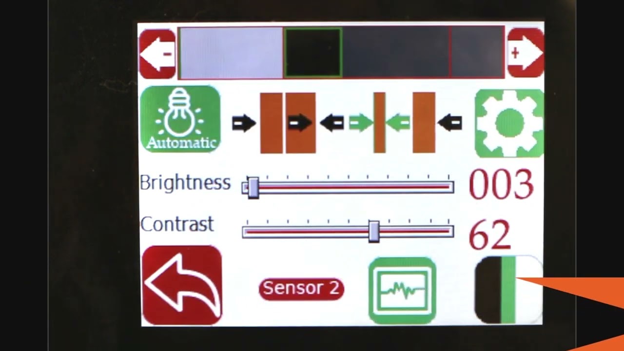
hello everyone today we're going to talk a little bit more about width measurement but this is more like an advanced width measurement application one of the things that you're going to see in the industry is that different people provide width measurement based on the edge position there are certain applications where you would need to measure the width of the web not based on the edge of the web but some contrasting feature on the web for example if you have a lamination or embossing application where you have multiple layers of web and the web goes through some Heating and Cooling different layers of the web May contract or expand and this might change the width of the web and and if you're just looking at the edge of the web that may not be representative of the width change that is experienced by a feature on the web withdrawal to roll our sensors not only can detect the edge of the web but it can also detect some contrasting features on the web and will take advantage of that and with that we can also look at width of that contrast contrasting feature so we have a setup here where we're looking at a sample in the bottom right there and then we have one of our white light sensors the ODC 48 white light sensors installed there and it's looking at that sample and this is just to simulate how we would do a contrasting feature measurement application where the web is stabilized either on a backup roller or really close to a roller so that the plane of the web doesn't change and that's what that is simulating and then we have a controller here and the controller is actually set for contrast mode you can go in and you can see that it's set for contrast mode and then it's also set to provide the width as an output and we'll see how that we can set it up to provide the width output even though we have two sensors connected we have disabled one of the sensors we're only looking at One sensor in this particular sensor is Sensor 2 and it's set for contrast mode what we are going to do is we're going to measure the width of this contrasting feature right there it's hard to see in this image but there is gray region a black region and another little bit brighter gray region here as a first step we're going to make we're going to teach the controller for the feature that we want to this is very similar to tracking so if you want to track this feature you're going to do the same thing press this button to unlock the teaching mode and depending upon whatever feature that you want to pick you can scroll through it in this case we want to pick this black feature right there we have selected it the contrast mode that we have this is the line mode so we have detected that and then lock in on it and if we go to the home screen you're going to see the the contrast the middle of the contrast representing the contrast is chosen as in line mode and then it's also showing the width of that feature so if I move my sensor back and you should be able to see that the width change a little bit but it also keeps track of the position one of the things with this particular mode or line mode is that in order to lock on this contrast there are two conditions that needs to be met one of them is the width of the contrast and the other one is the color of the contrast or the brightness of the and this is intended to make sure that we don't jump from one to another contrast and if you are measuring the width with this particular feature then whenever the width changes too much or the color changes too much you're going to have the measurement you're going to have no measurement what I mean by that is if I go in here and then pick the next line this is still a black line but you can see that the width went to zero even though there is a black line that you see here that's because of it it lost that contrast measuring the width of the web based on this contrasting feature is restrictive in line mode however we can go in and measure the contrast with in in other modes for example if you want to look at this particular width so this is the width of this region that you want to measure you can select that teach it then go to the home screen and that's showing you the width of that region and if we reduce that width you can see that that this region is 0.68 inches and then if we move further and further that region increases and it'll go all the way up to you see any other black region and now this is the measurement of the width the contrasting feature width and if we move any further the width is not going to change because it's bound by from this region to this region so we can not only measure the edge of the width of the width based on the edge we can measure the width based on any of the contrasting feature in the web so this is with one sensor how we do it some examples of applications is to measure the width of a die cut edge of a label to the edge of the web this is important in slitting certain slitting applications require the edge of the web to be at a certain distance from the die-cut edge of a lab or edge of the web to be at a certain distance from the edge of a printed mark on the web other applications are to measure the coding width in any type of coding or glue width or any of those kind of things lithium ion battery trim width measurement or tab width measurement or some other examples of this application where you want to measure the width of a contrasting feature the outputs that we provide is going to be very similar to the edge outputs so in this case we are using a 48 millimeter sensor and then this value is or we are using about two inch wide sensor and this value is about 0.68 inches so the output if it's an analog it's going to be proportional to the width of the sensor and again you can also get this output through the ethernet and if we look at that on our web browser we should also see the same output so again if we look at the output on our web browser it shows 0.685 inches and if I move the sensor and the width changes it updates that value again you can do it in millimeters if you want that's 21.7 millimeters or in inches it's 0.805 0.855 millimeters okay so that's a quick overview on width measurement based on a contrasting feature on the web with just a single sensor in the next video or in the subsequent video we will take a look at how we can do width measurement with two sensors based on the contrasting feature on the web
For a complete overview of web width measurement with Roll-2-Roll® Sensors and Roll-2-Roll® Controller please visit this page: https://r2r.tech/articles/web-width-measurement-and-monitoring-applications-and-technology
For more information about the SCU controller please visit: https://r2r.tech/products/roll-2-roll-controller
Transcript
Show full transcript (1174 words)
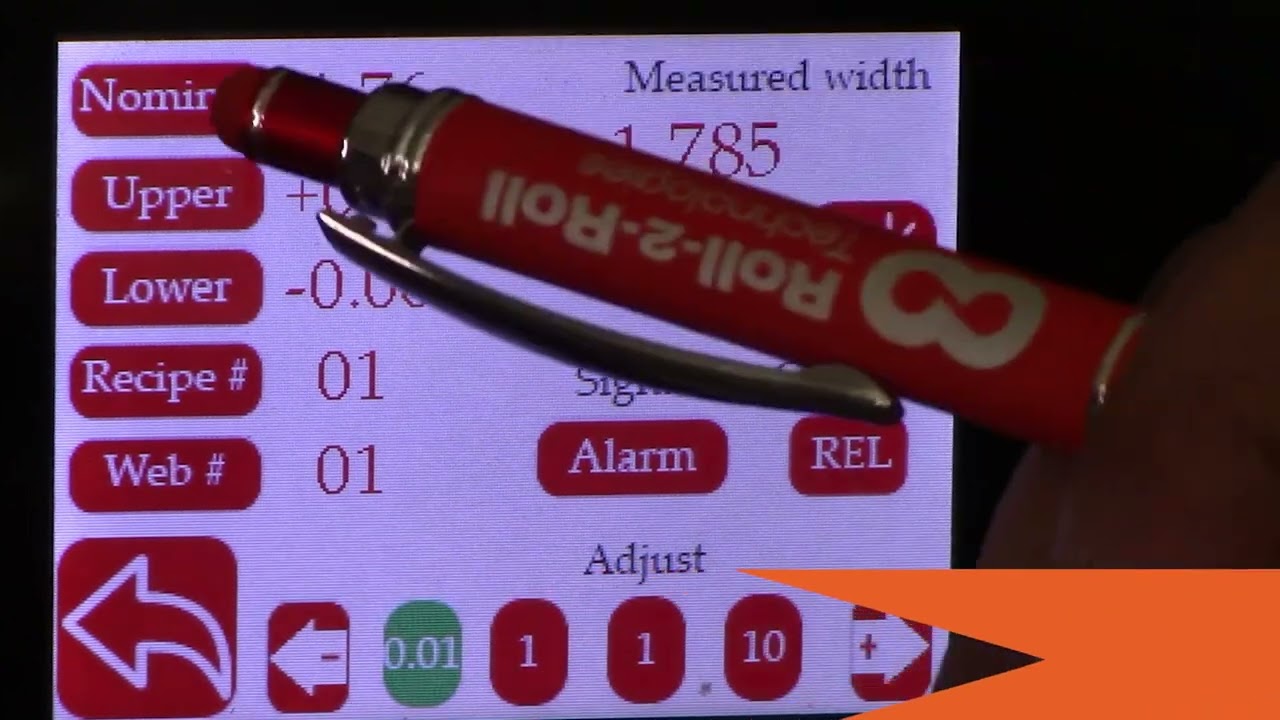
in this video we're going to look at how we can set up the controller scu5 controller for width measurement with two sensors I've got a couple of sensors installed here one is 112 both of them are 112 sensors one of them is looking at the left edge of the web and the other one is looking at the right edge of the web when we are doing width measurement with two sensors what we would ideally like to have is two sensors of the same range that means that if we have a 112 here we would also like to have the 112 there and then we also want to have the two sensors with the same orientation in this case this particular sensor has the connector coming on the right hand side this is behind the web it's on the right hand side and likewise for this connector it's coming on the right hand side and that's what we need because our camera has the pixel one here and then the nth pixel here and then for here the pixel one is here and we have the nth pixel there if we have one cable coming out this way and the second cable coming out this way this camera has to be inverted which is not ideal and it will not give you the correct output now if both cameras are inverted that's fine we cannot have one camera straight and the other camera inverted and that's an important thing that we need to keep in mind when we are using two sensors so we have those two sensors one is looking at left and the other one is looking at right we're gonna go into the controller and show how we can set that up so go into the tools icon power user sensor in this case we had sensor 1 disabled so we're going to enable that and we also have the sensor one looking at the left edge of the web so we're going to set that to left Edge and we're going to set that to right Edge for Sensor 2 and then again we're going to go into the operator screen go into the sensor a Sensor 2 image is pretty solid switch over to Sensor One the sensor one image is also solid but the only thing that we want to do is we want to make sure that this automatic brightness is set to freeze and then increase that brightness just a little bit so that we have that the web position is pretty close to the edge of the sensor that's fine if you need to move it you can move it so I'll just go ahead and move that sensor back in so that we have it within the range and there we go now we can go back to sensor two both sensors have the range set properly and then next we need to make sure that the output mode is an analog analog output mode is in width again we'll go back to 10 volts for now just for measurement purposes and then that's done and the final thing that we need to do is to actually set up the um the teach the controller for the width measurement so if we go back to the setup we can see that we have two sensors and the sensors are certain distance away from each other we actually don't know what the distance between them are and the easiest way for us to set that distance is to actually teach the sensors for that distance and again for all width measurement applications we want to make sure that the web is stable and we don't have any plane change so it's supported between two rollers here so it's pretty stable and we want to make sure that we don't change that while we are running in the sense of the plane change now in order to teach the sensor what we are going to do is we're going to actually measure the width of the web so it's about eight inches wide and go into the controller here and go into the tools icon operator width and just to make it easy I'm going to go to the units inches and go to width and then eight inches is the nominal width I'm going to set that to 8 inches and then I'm going to keep the output type as absolute and now I need to go in and press the teach button and then give it a few seconds and then accept what this teaching procedure is doing is that it's taking the nominal width entered in this controller and it takes the measurement from each sensor and then it computes the distance between the two sensors that's the way in which we're able to teach the controller for the distance between the two sensors as long as the the distance between the sensors are not changing as long as we are not moving these sensors if the width changed you don't have ever have to teach it again because the teaching procedure is only setting up the distance between the sensors and and there's no need for us to teach every time the width changes this is a one-time procedure and as long as all the settings are the same then we don't have to re-teach the just like the single sensor mode if you go in to the controller we can set the output type as absolute or header so if you set it as absolute the display value is going to provide an absolute measurement and if the width increased or decreased it's going to show that value so if I put in an extra one you can see that the value increased or decreased based on that now you can also set that up to oops set that up to error and in this case it's going to provide an error output so if I add something you can see that the error changed increased and that's essentially it so few things to keep in mind when we are looking at the width measurement with two sensors so we have the sensor position indicators here so we we got the sensor one as the left sensor here and Sensor 2 as the right sensor those are indicated and we have a split screen here the left side is showing the left sensor or sensor one and the right side is showing the right Edge or the Sensor 2 the green line here is showing the center line position of the web with respect to the two sensors and then the label here shows the width and then right now is showing the error and if we want to set it to Absolute and it shows the absolute value there that's how we set up the width measurement application for two sensors and in the following we'll also look at the analog output when we have two sensors
Web Width Measurement with SCU5 Controller: Digital Output to Drive Stack Light
Transcript
Show full transcript (614 words)
hello everyone this is arvind say shadri from Roll to roll Technologies today I'm here to talk a little bit about our width measurement system with the digital output we have a demo set up here where we have two sensors the odc48 set up for width measurement application and that was going to provide a digital output and we have a stack light in the back and that's going to provide an output based on whether it is within range or not in order to do that let's go ahead and first set up a few things I'm going to go into the tools icon here power user and make sure that both sensors are enabled one is set to left the other one is set to right and then can go in and make sure that the image that we are looking at is good Sensor One image is good Sensor 2 image is good make sure that both the brightness are frozen take a look at our previous videos for more information on how to set these things up both sensors are in Edge mode and now we are pretty much ready to go go and enable the width output so analog and if you set that mode to be width then you should be able to see that now we can go in and teach the system for the width of the web in this particular case the width of the web is six inches so I'm going to go in and set that up to six inches oh six right there okay and then I can do the teaching so I can teach and accept and now we have set up the width and basically what we did was we taught the two sensors or we thought the controller the distance between the two sensors based on the web that we already have and we also have the upper limit and lower limit for the alarm signal and if we press this then we have the warning signal we have the upper limit and the lower limit for the warning signal as well so we can set up both of these and once that is done we can either choose the output is relative or absolute and if you press relative then the screen is going to show just the change in width and then if you have it absolute it's going to show you the actual width itself let's go to the home screen and you can see that it's in relatives because we taught the sensor right now everything is fine we do have this threaded up with the web that has some width changes so one of the things that we are doing is that the same sensors that are used for width measurement are also used for guiding this is applicable as long as you don't have too much plane change in your guiding application so what we're going to do is we're going to turn it in auto start the web guide and let it run so this is showing the the real time with change but as you can see in this stack light right here when the width changes from there's the Green in the bottom and then Amber and red showing that as the width goes above or below those warning limits or alarm limits the output is going to turn on really simple system for width monitoring and like I said it can also be done with guiding at the same time for more information about our products and different application visit our website and subscribe to our Channel thank you