For a complete overview of web width measurement with Roll-2-Roll® Sensors and Roll-2-Roll® Controller please visit this page: https://r2r.tech/articles/web-width-measurement-and-monitoring-applications-and-technology
For more information about the SCU controller please visit: https://r2r.tech/products/roll-2-roll-controller
Transcript
Show full transcript (1174 words)
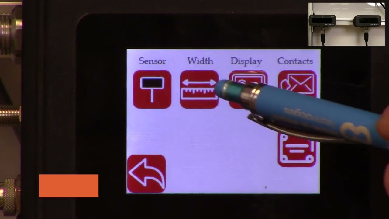
in this video we're going to look at how we can set up the controller scu5 controller for width measurement with two sensors I've got a couple of sensors installed here one is 112 both of them are 112 sensors one of them is looking at the left edge of the web and the other one is looking at the right edge of the web when we are doing width measurement with two sensors what we would ideally like to have is two sensors of the same range that means that if we have a 112 here we would also like to have the 112 there and then we also want to have the two sensors with the same orientation in this case this particular sensor has the connector coming on the right hand side this is behind the web it's on the right hand side and likewise for this connector it's coming on the right hand side and that's what we need because our camera has the pixel one here and then the nth pixel here and then for here the pixel one is here and we have the nth pixel there if we have one cable coming out this way and the second cable coming out this way this camera has to be inverted which is not ideal and it will not give you the correct output now if both cameras are inverted that's fine we cannot have one camera straight and the other camera inverted and that's an important thing that we need to keep in mind when we are using two sensors so we have those two sensors one is looking at left and the other one is looking at right we're gonna go into the controller and show how we can set that up so go into the tools icon power user sensor in this case we had sensor 1 disabled so we're going to enable that and we also have the sensor one looking at the left edge of the web so we're going to set that to left Edge and we're going to set that to right Edge for Sensor 2 and then again we're going to go into the operator screen go into the sensor a Sensor 2 image is pretty solid switch over to Sensor One the sensor one image is also solid but the only thing that we want to do is we want to make sure that this automatic brightness is set to freeze and then increase that brightness just a little bit so that we have that the web position is pretty close to the edge of the sensor that's fine if you need to move it you can move it so I'll just go ahead and move that sensor back in so that we have it within the range and there we go now we can go back to sensor two both sensors have the range set properly and then next we need to make sure that the output mode is an analog analog output mode is in width again we'll go back to 10 volts for now just for measurement purposes and then that's done and the final thing that we need to do is to actually set up the um the teach the controller for the width measurement so if we go back to the setup we can see that we have two sensors and the sensors are certain distance away from each other we actually don't know what the distance between them are and the easiest way for us to set that distance is to actually teach the sensors for that distance and again for all width measurement applications we want to make sure that the web is stable and we don't have any plane change so it's supported between two rollers here so it's pretty stable and we want to make sure that we don't change that while we are running in the sense of the plane change now in order to teach the sensor what we are going to do is we're going to actually measure the width of the web so it's about eight inches wide and go into the controller here and go into the tools icon operator width and just to make it easy I'm going to go to the units inches and go to width and then eight inches is the nominal width I'm going to set that to 8 inches and then I'm going to keep the output type as absolute and now I need to go in and press the teach button and then give it a few seconds and then accept what this teaching procedure is doing is that it's taking the nominal width entered in this controller and it takes the measurement from each sensor and then it computes the distance between the two sensors that's the way in which we're able to teach the controller for the distance between the two sensors as long as the the distance between the sensors are not changing as long as we are not moving these sensors if the width changed you don't have ever have to teach it again because the teaching procedure is only setting up the distance between the sensors and and there's no need for us to teach every time the width changes this is a one-time procedure and as long as all the settings are the same then we don't have to re-teach the just like the single sensor mode if you go in to the controller we can set the output type as absolute or header so if you set it as absolute the display value is going to provide an absolute measurement and if the width increased or decreased it's going to show that value so if I put in an extra one you can see that the value increased or decreased based on that now you can also set that up to oops set that up to error and in this case it's going to provide an error output so if I add something you can see that the error changed increased and that's essentially it so few things to keep in mind when we are looking at the width measurement with two sensors so we have the sensor position indicators here so we we got the sensor one as the left sensor here and Sensor 2 as the right sensor those are indicated and we have a split screen here the left side is showing the left sensor or sensor one and the right side is showing the right Edge or the Sensor 2 the green line here is showing the center line position of the web with respect to the two sensors and then the label here shows the width and then right now is showing the error and if we want to set it to Absolute and it shows the absolute value there that's how we set up the width measurement application for two sensors and in the following we'll also look at the analog output when we have two sensors
Transcript
Show full transcript (356 words)
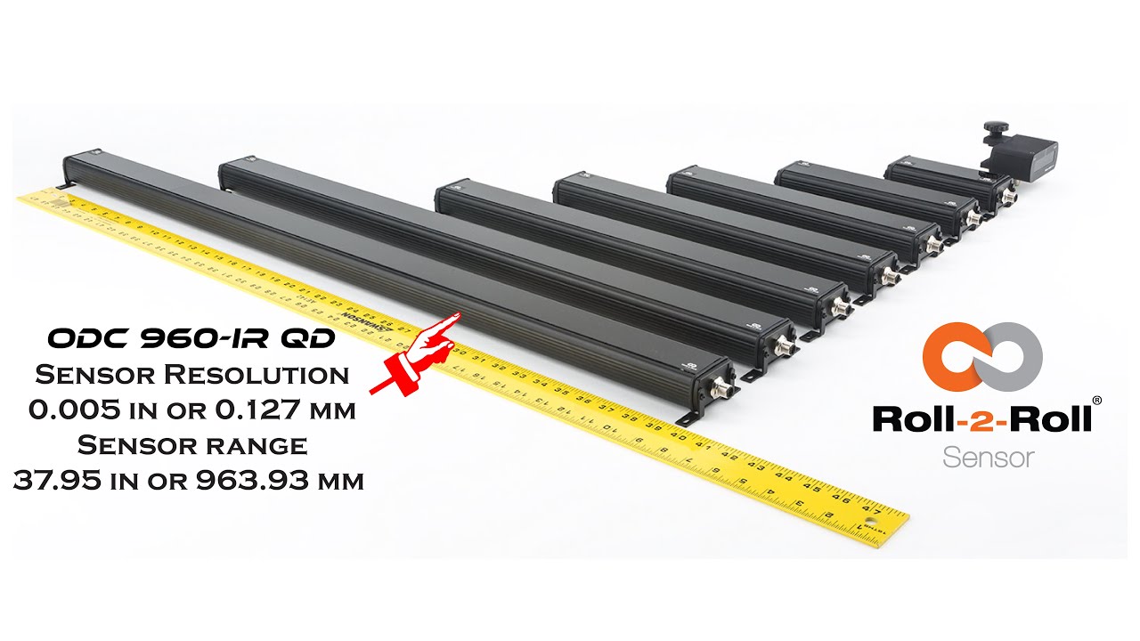
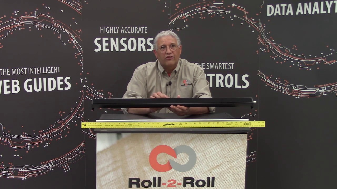
Hello everyone, this is Aravind Seshadri from Roll-2-Roll Technologies. Today we are really excited to talk about one of our newer products for edge guiding, sensing and different applications. We have our ODC 960 this is one of the widest edge sensor that is available in the resolution of 5 thousand's of an inch and this is one of the higher resolution cameras that we have for such a wide sensing range. There are lots of applications for this including web guiding, width measurement, thread counting, flag detection, splice detection.
Some of the unique features of this system is that it is a one sided solution. So when you have a one sided solution you don't have issues when you are trying to install it in a compact space. Becasue if it is one sided you can install it vertically or you can install it facing down so that you don't have to worry about the dust accumulation on the sensor. It also occupies a This is an unique and proprietary technology where we have our linear optics.
This allows us to install the sensor really close to the web. So even though the field of view is pretty wide. You don't have to worry about trying to have a large working distance. We don't have that issue.
And also because we have the linear optics we have a 1:1 magnification ratio. That means that we have a really good resolution in terms of the image that we are capturing. If you compare that to traditional machine vision system with a circular optics, when you increase the field of view your resolution goes down. In our case our resolution doesn't go down.
Right now we have plugged it up with our SCU5 controller where you can get about 5 thousands of an inch resolution. This can be used any of the applications we already support. Anyway we are introducing this at the converters expo show 2023 in Greenbay. And it should be available this summer for purchase.
Take a look at our website and we will have more information about the sensor and feel free to contact us. Thank you!
Transcript
Show full transcript (3927 words)
hello everyone today we are going to talk a little bit about the web width measurement application and how we can use the scu5 controller to measure the web width and also use another plc to collect that data log that data and also save it in a csv file on a usb thumb drive in order to do this what we're going to do is we're going to first set up our se5 controller for width measurement mode and then we also offer the rti which is the plc which has a special program that would actually talk to the scu5 controller and then allow the user to connect a usb drive to the plc so that the data can be logged automatically in the plc and the communication between the plc and the sco5 controller is being done through ethernet ip and then the user also has the ability to set up lot numbers so that when they are tracking different product codes they can enter that and that information is saved in the usb file automatically and the plc also allows the user to start and stop the data collection based on a line signal so that the data is only collected when the web is running and when it's not running the data can be automatically stopped from data collection and then finally we can also connect that plc to a stack light directly so that we can provide the alarms for warning error and then all good signals so all of this can be done uh through the plc and that's what is shown here this is the plc that we would be using to do that the first step in this process is to make sure that we have the suv5 controller set up for web width measurement mode and then the second step is to make sure that the ethernet settings on the sc 5 controller and the plc matches and then the third step is basically setting up the parameters on the plc so that you have everything for triggering the stack light as well as data logging so those are the three main things that we are going to cover so first we'll start off with setting up the se5 controller for width measurement mode as you can see here we have the sco5 controller now ready and then we also have the two sensors up on the top right corner and we're using two sensors one for detecting each edge of the web we'll go through this process so that we can set up the controller for width measurement as you can see if a web is presented you can see that both edges of the web are seen by the two sensors and then once that is there we just need to set the controller for width measurement mode and that can be done by following these steps first we're going to go into the tools icon right here and then go on the bottom power user and then go into the analog mode and make sure that the width is selected here and when we select this as the width now the home screen now shows the width as the output the controller still doesn't know the distance between the two sensors so in order for us to do that we need to teach the controller for the width so if i present the web here it's going to give some random values there so in order for us to teach that the distance between the two sensors we're going to go into the tool cycle and again and then the top right icon is the operator icon we're going to click on that and we're going to click on the width mode and then a few things that we are going to set so that we can teach the controller for the right measuring mode first of all the output type we're going to change it to absolute and then the nominal width this is going to be the width of the product that you're going to present while you're teaching so in this case the width of the product is approximately about 5 inches so i'm going to set in 5 inches right there and you can use this icon to change that and then the upper limit and lower limit it does not matter for this application because we're going to use the data raw data through ethernet to take care of that so we don't have to worry about that and now at this point all that we have to do is to present the web and then teach that while the web is presented so that's what i'm going to do right now so once we present the web and the teaching is accepted now we can go back to the home screen and now the controller is set up for width mode with two sensors and then now it's showing you the absolute width of the product as we move the web when the weight changes you can see that the width of the product also changes so the next the second step is that now the data is being collected in the scu5 the data is sent through the ethernet it's not being logged so in order for us to log that data we need to be able to set up the network parameters so that we can take care of these so the second step is to make sure that the network parameters are set up the easiest way for us to find out what is the ip address of our device and also set the network parameters is through the operator interface directly so we can do that by going into the tools icon the power user icon and then go into the communication we want to make sure that the ethernet is on as shown here and depending upon your network settings you may or may not want to have the dhcp on and then ftp on that really doesn't matter for this application if a network device is present then the controller will actually show the type of industrial network that is here and this is called ethernet ip and for in our case ethernet ip is the type of industrial network that we are using depending upon the firmware version you might have something here that says what type of module that we have we have two types of modules hms as well as hillshare depending upon what module you have that will show up if you have a older version of the firmware let's say version 3.6 d or maybe even 3.6 a then the type of module will not show up there the ip address of the module is shown here the subnet mask is shown here the gateway is shown here and then the mac address is shown here if you want to change the ip address of this module then you can just press this ip button and then type in the ip address that you want to change so i'm going to say 192 0 0 and 1 100. this is just for illustration purposes i actually put it as 2.100 if you want to set this you can press the set button to set it because i set the ip address wrong so i'm going to go back in and put the right at the address so again press on that one ninety two one sixty eight zero zero one and one hundred once we do that we need to press the set at the address to have the ip address set based on what you have entered and then if the ip address is different than what you had before you can hit the refresh button just to be sure that the controller has taken the ap address in some of the cases we might have to restart the whole controller especially with older firmware we might have to anytime we make a network change we might have to restart the power cycle the call controller with the newer firmware and the chip that we have we don't have to do that but likewise you can do the same thing for the mask and gateway and then if you have a controller or network where you are setting the dhcp then you would turn on the dhcp and anytime you turn on or off the dhcp you do need to power cycle the controller but essentially that's the easiest way for us to set the ip address the network information and also to view what controller or what module that we have on this particular controller there's also ways in which we can set these network information through a computer we're not going to talk about it today but this is the easiest way in which we can set this up now the second step in in this process is once we have this set up now we're going to go to the plc and make sure that the plc has the right parameters for communicating between the seo 5 and this controller the easiest way to make sure what the plc network information is and what the ip address for the plc is is done by actually pressing on the top left and the sorry the bottom left and the top right corner of the plc several times okay once you have that then you can go in and click on the offline so once you get into this offline mode you can also ensure that the ip address for the plc is set properly and make sure that it matches with the network information on the su-5 controller you have the ability to connect the suv5 controller to a managed or unmanaged network likewise you can do the same thing with the plc or you can directly connect the plc to the sc 5 controller without going through a switch if you do that what we need to make sure is that the network information on the plc matches the network information on the sco5 controller and then plc has a distinct ip address compared to the sco5 controller and then the plc also knows the explicit ip address of the seo 5 controller so in order to check all of these things what we can do is we can go into the offline mode as shown here once you are in this offline mode we can go into the main unit and then click on the ethernet and then click on the lan and now this shows the information for this plc so this is the ip address subnet gateway for this plc we just need to make sure that this information is similar to the information on the scu5 controller so let's go ahead and look at that c5 controller communication and the ip address for the se5 controller is not the same as the plc which is what we want the subnet mask matches the gateway matches and then if you compare that with the plc has an ip address of 10 the sg5 has an ip address of 100. so once that is done we can go back into the peripherals and then look at the device plc settings ethernet ip and then go into that device and this is actually the device that we are trying to connect in our case scu5 so that ip address of that u5 matches the ip address on the plc now we have set up the plc and the se5 with the right network information so that they can talk to each other okay once we have all the ap address set up now we need to go into the steps that are necessary for data logging and also to start the communication first and foremost what we want to do is we want to make sure that the communication between the plc and the sg5 controller is going properly and for that we're going to go into that communication screen and then right now it says the ethernet ip is actually off so let's go ahead and turn it on now the ethernet ip is on if you don't see any error messages then it means that the sg5 controller and the plc is communicating properly just to show you what happens if it doesn't communicate i'm going to remove the ethernet connection from the se5 and you can see that there will be an error message that will show up saying that the tcp connection is lost or things like that so if you see that error message that means that the either the device is not set up properly to communicate with the seo 5 controller and this would be the error message that you would see um and it shows that that's not the plc it's basically it's not able to connect to the sco5 controller so as soon as we connect the cable back this error should disappear within a few within a minute or so and then yeah likewise now it's communicating with the plc with the suv so once that is set up so when you have a web in front now this should provide you the width of the web on the plc but it's also showing that width on the su-5 controller so in order to change the units what we are going to do is actually go into the setup screen and then go into the other setup as well and then the units are here you can set that to inches even though scu5 may be set to inches the plc can be set to another unit irrespective of what the unit of the scu5 is and in this screen you can also change the language currently we support english and spanish so if you press spanish it's going to go to all the icons would change to spanish and then if you want to set things back to english then you can do that so this is where you would set the units and you can go back to the home screen and now if we present the web now the units would be in inches just like what the sc5 is now we know that the sco5 is communicating with the plc and then you are able to see the data now we can add more things to it so as you can see on the home screen there are the three lights that are available these are the three digital outputs so in order for us to run up a stack light what we do is we take the data from the scu5 and then use the recipe or the settings that are there on the plc so that you can set up upper limit and lower limits for the alarms and warnings that way you can connect it to a stack light and the stack light would go on based on that so in order to do that we're going to go into this screen and then go into the width setup and we can set the upper limit and lower limit for the alarms and all the units are going to be in the respective units for the alarm and as well as the width so the first step that we want to do when we are in this which setup screen to trigger the stack light is to set up the nominal width the alarm warning and all this information so in our case we have set the nominal width to 5 inches but if you want to change it to some other value you can just press that button upper limit and lower limits for the alarm and the warning doesn't have to be symmetrical so it can be asymmetric the alarm value should always be greater than the warning value uh that's the precondition when the width value exceeds the alarm value or goes above the upper limit of the alarm value or goes below the lower limit of the alarm value then the red light is going to be indicated and then likewise if it's in the range for the warning it will be in the amber and then if it is within the nominal width that's going to show the um essentially the green so once we have it set up we can go to the home screen you can see that right now the alarm is enabled and then when the width is within the nominal range you have it as green and then if the width changes to some value that is outside those limits amber and then if it's really off then it goes to red and that's the way in which this works now you can also plot this data so you can see that in a real time graph it's going to show you the the limits for the width as well as the limits for the alarm showing that in red so you can have a visual indication of how it's been doing starting with the graph like that now that we have set up these alarms and warnings and stuff like these are not used for data logging purposes but these are just for triggering out triggering the stack in order to lock the data you can start logging by connecting a usb and if you want to have some lot information you can go in and press that and enter your lot number so that when we log the data that lot number is also allocated there so in order to log the data we need to be able to connect the thumb drive there's a usb port underneath the plc that we can use to connect that thumb drive so i have an extension cable here so i'm going to connect the thumb thumb drive through an extension cable but as soon as we connect that thumb drive to the plc there should be a blue icon that appears in the bottom right as you can see in the bottom right hand corner that icon appears and if you want to take a look at it go inside right now it has disappeared but that lets you know that the usb has been recognized and connected to the device once you are ready with that what we can do is go into the plc and start data logging so we have the web here and we have presented all the uh the settings for the upper limit and lower limit and all those kind of things so since they're all set up right now we can go ahead and start collecting the data and when the web is there you can see that it's measuring that we're going to go away and then communication data log now it's saying no data logging is being done so in order for us to do the data logging i'm going to start and now this is started data logging the remote data log is off right now but if you want to have a another interface or a signal that would tell us when to lock the data i went to start i'm going to stop then you're going to enable that if you want the operator to start and stop the data logging then you can just go here and do it since the logging is being done it says logging data on the top left hand corner and then once you're done data logging you can just press the stop button right there and then if you want to remove the usb you can safely remove the usb by pressing the top and the bottom just like what we did before and then now it shows up the usb icon at the bottom there so we're going to click on that icon and then say remove usb storage device and press yes on it and then the storage device has been removed successfully because that icon on here has disappeared now you are able to disconnect the usb thumb drive and once you connect it to the computer then you have the ability to take a look at the data so let's do that next okay we're going to switch over to the computer screen now the usb is connected and you can see that the thumb drive has been recognized and it shows the different files that are there so today is the 25th so we have that file right there showing the 25th and if you double click on that file you can see that it has collected the data the lot number has been assigned and then you also have the sorry about that you also have the width data that is being presented here as you scroll down okay as you scroll down you can see the actual width measurement that was done so right now the time scale is about in this particular program it's about once per second so the width at that time was 4.735 inches and the units is basically the same units that we have on the controller so if you had units the unit shows up and if you have inches it shows up the lot number shows up and then the time when it was recorded and then the date when it was recorded so that's as simple as that to be able to log the data through the rti plc um in from our scu5 controller one other feature that we have is that we also have the ability to provide some recipes the recipes are used when you are running different web with products and you don't want to change the nominal with the alarm and the warning information every time you change the width you can create your own recipes and that's done here and um anytime you want to load a recipe you click on that product product number and then you're going to press load recipe and whatever that value is going to be loaded it's going to be displayed it will not be presented or pushed to the home screen until you press the accept so now once you press the accept that value is being loaded anytime you want to save a new recipe you're going to go in there press on load and then press the values for those so if i want to change that nominal width to 5 inches i'm going to enter that nominal width and then the all the other settings are set now i am happy with this recipe so what i'm going to do is i'm going to save that now product one every time we go to product one it's gonna have the five inches so we go back to product two load that recipe that shows up there and product one come back here and load that recipe now it's five this is just displaying it so if you want to push this to the home screen you still need to press accept and we're gonna do that now if you go back to the home screen that's gonna show you that the new alarm and warning signals and you can see that here if i present the web you can see that it's good now and it's an alarm now i think so that's essentially it
Roll-2-Roll Technologies would be introducing the WPS 900 sensor, one of the widest sensors that in the market. With over 35 inches of sensor range, this is one of the widest edge sensors, if not the widest in the converting industry. Please come visit us at the booth to find out more.

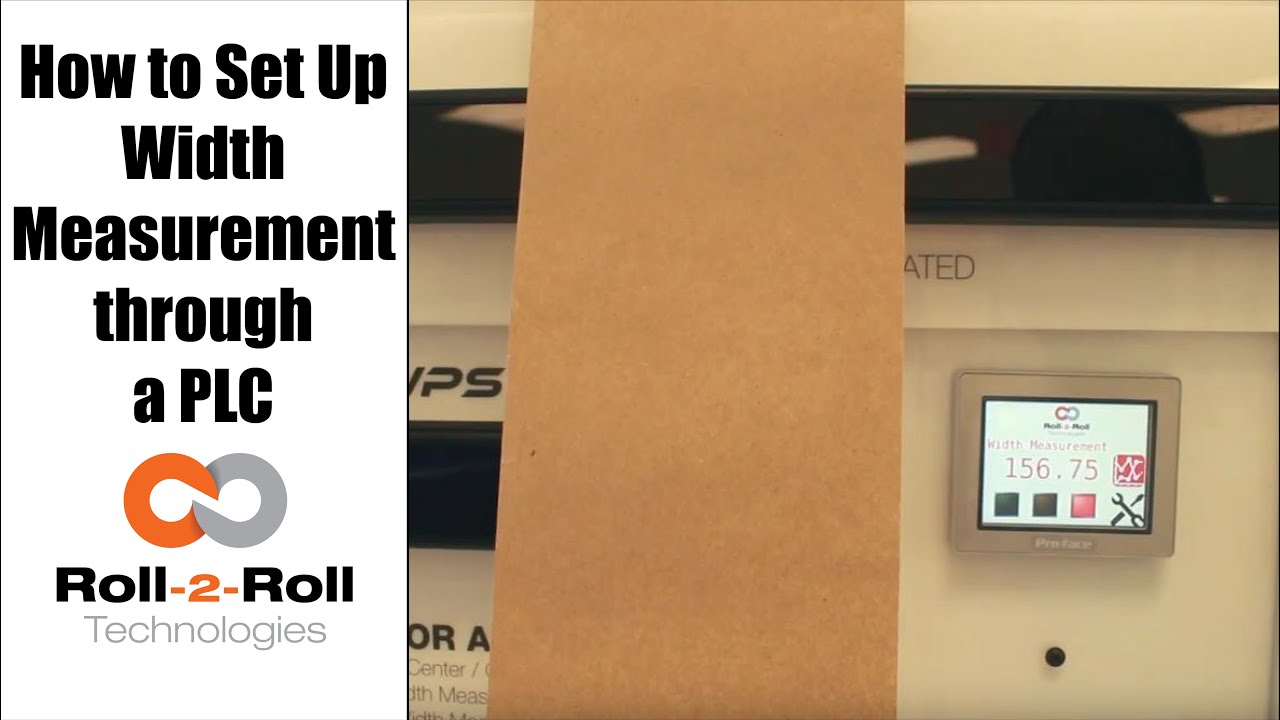
A programmable logic controller (PLC) or programmable controller is an industrial digital computer which has been ruggedized and adapted for the control of manufacturing processes, such as assembly lines, or robotic devices, or any activity that requires high reliability control and ease of programming and process fault diagnosis.
In this case, Roll-2-Roll Technologies programs the PLC for web width measurement in converting operations.
Transcript
Show full transcript (687 words)
okay this is a short video about how to set up the width measurement sensor now the first and foremost thing is the sensor has to be connected to the power supply and to the Ethernet and then a cable goes into the PLC and power for the PLC and for the Ethernet as soon as we tried a new web we present the web take a look at the documentation on our website to say how far the web needs to be with the sensor but once you have that ready we can go into this settings screen and then go to wit setup this is where we would go in and set up what is the nominal width so whenever you start a new job you can probably measure the width of that in this case I've already done that it's 153 millimeters so I'm gonna go in and set hundred and fifty three millimeters that's my limit and then we're gonna press record wait it's going to save that as the correct width we can also set alarms and warnings so depending upon your application so in this case we'll go ahead and set an upper limit of one millimeter for an alarm lower limit of one millimeter for the alarm and then about 0.5 millimeters on either side for the warning these ranges are the ones that are going to trigger the stacked lights so whenever the web width is within the nominal width which is 153 millimeters in this case then you'll have the green light enabled and then when it goes about by about 0.5 millimeters you're gonna have the amber light enabled and then any time it goes about one millimeter you'll have the red light enabled so go to the home screen and you can see that since it is within the spec the greenlight is enabled anytime I go and it increases quite a bit then the red light gets enabled and if I just tilt it a little bit and the weight goes up by half a millimeter then the amber light gets enabled one of the other things that we could do is actually trend the data so as soon as you set the limits the upper and the lower limits so we set it as one millimetre so 153 is our normal width and then we have 152 as the lower limit and 154 is the upper limit and it trends the data anytime that the weight changes they're gonna be able to see that the current measurement is shown here and then a plot for about 30 seconds is shown there so that's about it so if you have jobs where you can do recipes you can go into this and you can start saving those recipes here so you can pick one of those and say load and then you can add those recipe there so you can say product one I want to put the nominal with - 150 millimeters or whatever that may be alarm is - warning is 1 and then you say safe so now that product 1 recipe is saved to that so if you want to load a certain recipe click on that recipe click on load it's gonna load that we go back to 1 and load that we got that whatever that we uploaded will go in now if you want to take this data and put it into your main screen you have to select that product and say accept then that will be the current value for the value so it automatically took that recipe and put it at 182 millimeters the range that we set alarms that he said automatically goes in there so since that's not the right one so let's just go ahead and load it and then put our current value there save accept and now we set our current weight to be 152 which is outside our limits so you got the amber light and then whenever you need to plot it we can plot that data right there so that's a brief overview of the weight measurement with our PLC's you
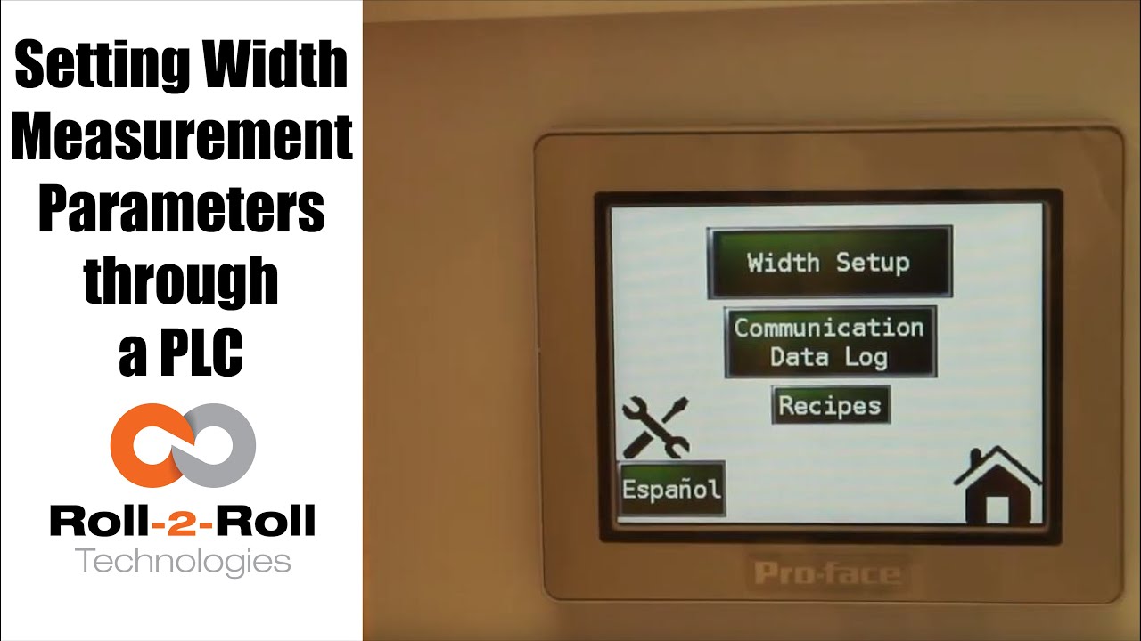
A programmable logic controller (PLC) or programmable controller is an industrial digital computer which has been ruggedized and adapted for the control of manufacturing processes, such as assembly lines, or robotic devices, or any activity that requires high reliability control and ease of programming and process fault diagnosis.
Transcript
Show full transcript (1078 words)
so in order to set up the Center for British Mint and we'll go over this menu once one more time we're going to go to the setup screen right here and then click on width setup then we can enter our nominal width the alarms the warning ranges and all those things first we want to whenever we have a new product in there we want to measure the product what the width of the product is in this case it's 153 millimeters we're going to enter 1 5 3 enter and then we're gonna set the warning to be point four millimeters so if the alarm is less than the warning the system will not accept it so the best way to do that is to make sure to set the alarm first so we'll set the alarm at 1 millimeter and there is a way for us to set a symmetric alarms so the positive range can be 1 millimeter and the negative range can be 0.5 millimeters if we want it to so in this case I'll set it at at 0.8 millimeters and then the warning range in this case let's set it to 0.4 millimeters and we have set everything what we want to do is to say hey this is the right one so we say record wait what it does is it teaches the sensor to say hey this is the nominal width we're looking for and I have presented the web with the right width and it'll take the measurement from then on so if you go back to the home screen it's going to show you the measurement and as long as it's within the range you're gonna have the green light whenever it goes to the warning limit it's gonna go to Amber and then whenever it's about the alarm it's gonna go to the red light these are actually also triggering a digital output on the PLC so we can connect a stack light with three outputs so connect the red sorry red amber and green to the three signals in the stack light the other thing that we want to point out a little bit more is the recipes so sometimes you might not see it you just have to click on this to say display recipe so what we have provided is an option for you to save seven different product recipes you can scroll through them and let's say we want to pick up product seven and we want to use that as the recipe what you need to first do is pick that number click on load and it's going to load the data here right now it doesn't have anything so let me go to one which has something ok so now I loaded product 1 and it had some values there so we'll have to load it once you load it it's loading is just for display purposes you need to press accept to accept that recipe so that it will be sent to the front screen for width measurement in this case I want to make sure to make some changes if you want to make the changes you can directly click on that width value and I'm going to enter 153 and then alarm as one date and then warning as 0.5 once I enter that if I press accept it's gonna send it to the front screen if you ever change a recipe you need to make sure to save it so right now I can press save now it saves it to the memory so that means that anytime you go back to that recipe and come back to one it will retrieve that data so make sure to remember to save it so two things one is if you want to load something it loads it here so we want to do that loads it here and if you want to take this recipe and put it into the front screen you need to press accept and any time you change the recipe you need to make sure to save it so that's the thing about recipes you have an option to say about seven recipes here there is also an option to log the data as you make the measurement there is a USB on this PLC so what you can do is you can connect a USB there and click on start logging it will it will start logging the data and whenever you're done you're gonna say stop logging and it'll stop logging the data and then you can take the USB off from there there are a few other settings here that you can set up as well these are advanced settings there is an option to override the minimum contrast in our sensor the minimum contrast is used to say whether something is an edge or not in the picture so by default we have 50 so we can have that and if you want to enforce that you need to press this button so that it changes into lime green instead of dark green whenever you want to disable you press that it disables that and this is the place where you can enter the value you can also make the sensor provide the data that is already filtered so if you want to do that you turn on the filter turn the lime green turn off the filter it goes off this is an advanced feature which is called as a minimum measurement quality whenever we take a measurement we have an output called quality factor and we can set that nominally it's ten millimeter ten is the minimum quality factor now if you want to make it higher you can set that value and enter it there so as long as there is a value it's going to take this value if you want to disable that option press n zero so I press ten and enter and it'll be that that's the minimum that you can provide so this screen is more like an advanced screen your operator wouldn't really have to do this only people engineers that are setting up the system can use this for troubleshooting purposes and stuff like that and yeah that's about it so these are the features there and like we talked about before we also have the option to log the data and showing the log of the data right here you
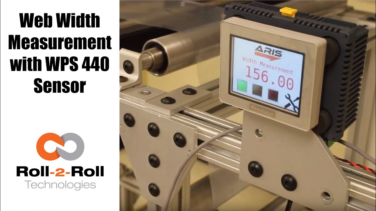
Roll-2-Roll Technologies offers robust width measurement capabilities with the WPS 440 Sensor. Using a PLC connected via ethernet, we are able to accurately measure the width of any material.
Transcript
Show full transcript (1727 words)
well today we just want to show a little bit more about our width measurement application with our 440 sensor so we have the 440 sensor installed and then you have the web coming over it we have installed two support rollers so that when the web moves it doesn't flutter too much we want to avoid fluttering whenever we do web width measurement this sensor is actually connected to Ethernet IP so you can connect it to a a PLC like this or we also have a web browser interface on the computer that you can connect to so the main things are here is how far the sensor is from the web right now we have installed it at about 5 millimeters from there that's the optimal distance that we recommend the sensor is installed facing up that is good but just to avoid any dust and other accumulation it may be better off to face the sensor down so that it's looking down towards the web a few other things that we need to consider is the the the free space behind the sensor we want to maintain about six inches of free space so that nothing in the background is seen by the sensor that's the optimal way in which we can get the best results there's also a way for us to get the maximum scattering out of the sensor if you want to do that what we would do is we will raise up this roller so that the web comes at an angle now about 10 15 to 20 degrees is the angle that we want and it depends upon the orientation of the sensor so if we if you want to get the maximum scrap scattering what we will do is we will raise up this roller so that the web comes this way but those are the few things that you want to consider before installing our 444 width measurement application other things to consider is this free span doesn't have any twisting so we don't want to install the sensor right next to a dancer roller or right next to a web guide we want to install the sensor between two fixed rollers so that we have a fixed pan and then web doesn't flutter that will be the ideal scenario what we were going to show right now is how do we get this up and running right now as you can see we have the power on to the sensor it's connected to Ethernet IP right now it's connected to a network device like a router or a switch so you can connect to the sensor through the network if you don't want to do that you can directly connect the sensor to the computer or you can directly connect this to your PLC or our PLC for that matter so just for demonstration purposes we're going to connect it to both the computer and the PLC to a network the next thing that we want to do is to connect the sensor to the PLC one of the first things that we want to do is find the IP address once the sensor is connected and powered up and connected to your network device we can pull up a utility called IP config we have information about that on our website we can go once you open up open up open up that program it will show what device there is and what's the IP address of that right now the device is said to have DHCP set automatically and it has an IP address 0 dot 0 dot 0 this is happening mainly because the Gateway doesn't match so what we would do is to make sure that they get the Gateway matches let's do that the Gateway is one one sixty eight dot one dot one and AP address of this device so right click configure on my parents one point something see you so once we do that we set a static IP address with the Gateway and everything now we can right-click and pull up a web browser and that's going to bring up our dashboard so this dashboard basically shows us several things the web measurement is shown here so this is the web in that the width measurement is 155 and something millimeters we also have a filtered width measurement we have a filtering algorithm that would take the filtered value of the raw measurement and then edge location which is left edge so that's saying where this edge is and then the right edge is showing where the other edge is and then within our software we also have what we call it as a quality factor which is basically think of it as how good of an image or how good of an edge that is so it says that the left edge has a quality factor of 300 and something and the right hand has a quality factor of 100 and something so this is a easy and quick and easy way to test our sensor make sure everything works fine we have a plot that shows the weight the measurement we also have other things that we can do with the sensor in terms of adjusting the brightness all of these are shown here so the idea the main thing that we want to do is make sure that the quality factor on the both edges are pretty high and as we mentioned before one of the things that improves the scattering is angling the sensor either we can lift this roller up or angle the sensor so that we get a pretty good quality factor so if you can notice when I move that since we don't get a good scattering the quality factor went down but if we install the sensor at the right about 15 degrees angle then we get a pretty good quality factor signal and then you get the measurement there so this particular web browser interface allows you to pan the data plot the data you can also save the data if you click on the save it stores that data as an excel file with all the information that we collect which is shown here such as the brightness and and the edge position and the width and everything so that's basically about the the web browser interface as you can see we can run the web and it collects the data as the web is moving over the sensor let's move on to the PLC and kind of show you how we can set up that PLC this is a special software that we install on it basically for customers who doesn't want to set up their own system they have the ability to use our PLC that we supply to do width measurement and also have the ability to provide a trigger measurement whenever the width varies so one of the first things that we want to do to get the PLC communicate with the sensor is to tell the PLC what the IP address of the sensor is in order to do that we're going to press these corners one after the other and then go to offline and this shows up the main screen here in the offline menu we click on peripheral and within the peripheral we're gonna select Device slash PLC setting and here we're going to use the ethernet/ip explicit messaging protocol so that's the one that we're going to select and then these settings are fine which is the standard setting the main thing that we want to set is the IP address of the device so we're going to go click on device and then set the IP address so right now it's set to 192 168 1 8 so our sensor IP address that we manually set was 192 168 1 dot 100 so we're gonna type in 100 enter and exit and then Save Changes so now the PLC is going to reboot with the new IP address we just have one more step to do to connect the PLC to the sensor or connect the PLC to communicate with the sensor and that's to enable the Ethernet communication so in order to do that we're gonna go into the settings and communication and turn on internet might be once we do that now we got the measurement from the sensor so this is the real-time width from the sensor that is going here now if the customer wants to set a few things for example if they want to teach the sensor so that we want to avoid any inaccuracy in accuracies in the measurement what we will do is we will put the web where at the location where they desire it and measure the width of the web then let's say in this case it's 155 millimetres would go in and press this 155 and press record width now they can also set warning and alarm ranges so for example we want to say alarm is for 4 millimeters warning is for 1 millimetre and going so as long as the width is within that range which is 155 we taught the sensor for that width it'll show green and whenever the width goes about a millimeter high or low the amber would show up and then when it goes about the warning the red would show up so and that's pretty much it right now we're seeing the weight variation because of the curls and all these things in the web we're trying to show or simulate some of the things that you would see when the weight varies by these curling there's also an ability for the customer to set recipes so if they have different product with you can set what is the nominal weight what is the alarm weight what is the warning with things like that you can load them you can save them and so on and so forth and also there's an ability to connect a USB here directly and save the data through the USB on this PLC right here and this PLC can be connected to an signal alarm signal lighting system with green amber and red so that it's readily visible for the operator running the machine so that's pretty much our width measurement system using our WPS 440 sensor you

Check out the many capabilities our sensors have in edge, center, width, contrast and mark sensing. Our sensors require no calibration. These advanced sensor capabilities are shown here in this video.
Transcript
Show full transcript (756 words)
This Pedro Velasco with Roll-2-Roll Technologies And we want to show you a little bit more about our sensor technology and its different applications. So here we have a demo set up to show some of the features that are sensors have. Right now we're showcasing the 221 infrared sensor and on the left side you'll see the forty eight millimeter white light sensor which we used mostly for contrast sensing so we have already set up the Infrared sensor and we're going to do first let me show you the in the edge mode all the capabilities that it can do. So they can do so right now number one.
It can actually tell you exactly where the sensor is mounted and Which side is that it's that said its absolute sensing so as you can see it automatically detects a sensor And then it's affecting the edge on this side, right? but I Want [to] change it. Just press here if I come from this side? See it automatically detects no calibration needed for this operation.
Additionally we have other characteristics that we can do with this we can do something with this same sensor. We can measure width. We set it up to monitor in this case. It can be a pass or fail condition so now there's no material, so I'm gonna put a material here, and then I'm going to set a Condition and I'm going to set it up.
Let's say I want to accept two millimeters off That's accept so now it has recorded the distance that just width that I want right? but put another material, that's a different width It will leave me a fail condition because it's beyond the limits that I've all already set up over here So that's another characteristics of our sensors. We can also show you another which is the string mode right here for the 221 sensor if I present one string? will actually see one string.
But that is the same time you can also see two strings and you can see even Three and many more right, but the best thing that we can do is we can actually also give you the distance between the strings between the edge of the strings, so in this case is telling us between the third and First string there's Thirty six millimeters right however we can adjust this, prepare you with our system so that they can actually tell you the difference between individual strings Now let me hook up now our White light sensor so as you can see I'm just going to unhook our 221 sensor infarred sensor And then I'm going to just hook up The light light sensor as you can see it turns on immediately It detects it and of course a white light sensor can do edge guiding. All right Just this the other sensors You can do it from either side, it auto detects. But I can also select the mode So right now. It's going to do contrast sensing So it will tell me The position this contrast as you can see by that?
Green and Red bar right, but I can also tell you Not only that I can tell you the width of that So it gives us a 9-millimeter width, if I change it and see, it changes. of course, if I Had a steady hand this little better, [okay]? [okay], so that's one of us the many features that we have and that's with the white light sensor the contrast capabilities also, we [can] also give you a Mark so let's say for example. You have something like [this] We wanted to detect the mark, so as soon as the sensor sees it It will tell me that the mark is detective.
Mark detected. This comes across, so this has multiple applications if you had For example. We can actually give you the distance between marks through a one of our algorithms But the best thing we can do is, we can also do this with ultraviolet light and then you can have a mark with UV ink which can also be detected. So these are some of our capabilities that are sensors can do.
Of course now we're looking for other applications As we do our research in our developing products by right now these are available to you. Just give us a call or visit our website, and you can actually see your products there. Thank you very much