Converters can save money and time by installing a North American Web Guide Upgrade kit from Roll-2-Roll Technologies.
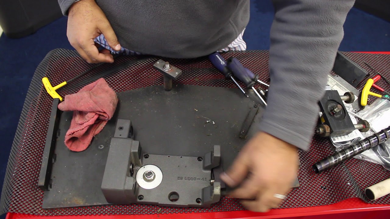
In the video we demonstrates the replacement of the actuator on an old North American Web Guide as part of the upgrade process with Roll-2-Roll® Web Guide Upgrade Kit, with controller, sensor and actuator.
The video shows step by step the process of removing the existing actuator and replacing it with a Roll-2-Roll Technologies actuator.
Transcript
Show full transcript (1100 words)
we're retrofitting our north american h5533 actuator wider web guides might have this cam roller smaller web guides may not have these two extra supports this is the pivot pin in the back of the webcam there's also a spring washer right here all these now we should be able to remove the top off that's what is inside so it should be a set of bearings here there's a washer right there the back of this we're going to have some needle roller bearings so let's just take them away and put it on right here and let's grab these doors uh bearings for me to grease them you need to grease them that's about it these two are the supports on the either side we'll just use them later on okay and we'll leave this in place here this is where the actuator is mounted okay so this is the old mechanism that they have there's a motor that's driving a pulley there's a gear reduction there and that pulley is actually connected to an even smaller pulley driving another pulley that's driving a lead screw so pretty complicated kind of mechanism when we go over our retrofit we'll show you how this is being simplified with our system we do not need to save any of these drive mechanisms because we're going to completely replace it with our actuator so well there's some more pretty small motor for a pretty big web guide actually now what we're going to do is remove the lead screw and in order to do that we need to remove this right here as you can see it's got threadlock red on it so let me put it back we'll try to make sure to put the same kind of red on it there's a small cover to the leech from the back so we're going to remove that and this is a spring which is used to cover the lead screw so that the dust and dirt doesn't go in uh the spring seems to be in pretty good shape so we're going to reuse it for a retrofit this is the old mounting recirculated ball bearings and basically you had the lead screw with the reach circulating ball bearings in it it does require some lubrication and stuff like that but we're going to go to a different kind of an actuator where the lead screw doesn't need to be lubricated [Music] just put it back in i'm going to make sure that this is smooth in this case it is not so we're going to take it apart and make sure to clean everything on this and see if we need to replace those bearings in there if not we'll just uh leave it as it as such and then put our actuator in there so this is the linear raceway mechanism seems to be pretty smooth just wasn't aligned properly here so when we put it on we make sure that it's well aligned when we install it and then make sure that this moves freely and then we'll put our actuator in these things on the end right here there are basically stops so that would limit the web guide from moving all the way through the raceway and stop at these tops these can be adjusted based on your need but for now in our case we're just going to keep it as it is and install the other things this is the servo center sensor right here we will replace it with our sensor so we don't need this one so we wouldn't need any of these let's see the other thing with these web guides is that they have this pivoting mechanism right here so when the actuator moves in and out in order to make sure that the geometry makes the web guide move along the rail uh you need some pivoting and that's why we have this in this part right here seems like it's a little bit tight so we're going to take it apart and check everything and then put back everything so that we can make it run smoothly again these are all needle thrust bearings so a couple of layers of them with the spacers in them that makes it easy for this to move so it does seem like just the just the tightness of this was not making it move properly so when we put it back in we'll make sure to tighten it appropriately so that it's not hard to move okay again we're retrofitting our north american h5533 actuator so for this particular actuator we have a mounting with our actuator and just a pivoting rod that basically holds the carriage so we have that so when you're ready to purchase the retrofit kit we'll supply an actuator with the appropriate lead screw stroke length and everything so that you can retrofit this one so let's go ahead and do that this would be facing this way and let's put these rods in [Music] the only additional thing is that these were the shoulder bolts that you removed unfortunately it doesn't fit in with our mounting bracket so we would supply a spacer with a longer shoulder bolt on it and we will use that to mount that onto the system right there and let's go ahead and get this finished and that's about it so do not forget to put the bearings these bearings need to go in here we check them out and these needle roller bearings seems to be fine so we're just gonna put it right there and put this one this one goes right here with this nut so right now just to show you more or less the final application or all the connections already completed we're just going to show you that we can jog already with our control we can jog our our motor in position furthermore if i just place my hand to use as a material a possible material i'll just put it in automatic and you can see how it moves the whole thing so there you go it's a pretty uh easy setup for us so if you have an old web guide such as a north american and you want to do a retrofit this is we can provide you with a retrofit kit you can either install it or in some cases you can send us a web guide to us and we can do the retrofit for you you
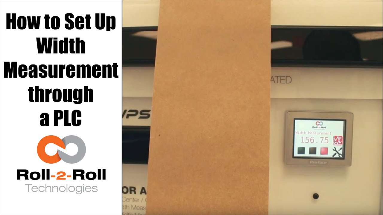
A programmable logic controller (PLC) or programmable controller is an industrial digital computer which has been ruggedized and adapted for the control of manufacturing processes, such as assembly lines, or robotic devices, or any activity that requires high reliability control and ease of programming and process fault diagnosis.
In this case, Roll-2-Roll Technologies programs the PLC for web width measurement in converting operations.
Transcript
Show full transcript (687 words)
okay this is a short video about how to set up the width measurement sensor now the first and foremost thing is the sensor has to be connected to the power supply and to the Ethernet and then a cable goes into the PLC and power for the PLC and for the Ethernet as soon as we tried a new web we present the web take a look at the documentation on our website to say how far the web needs to be with the sensor but once you have that ready we can go into this settings screen and then go to wit setup this is where we would go in and set up what is the nominal width so whenever you start a new job you can probably measure the width of that in this case I've already done that it's 153 millimeters so I'm gonna go in and set hundred and fifty three millimeters that's my limit and then we're gonna press record wait it's going to save that as the correct width we can also set alarms and warnings so depending upon your application so in this case we'll go ahead and set an upper limit of one millimeter for an alarm lower limit of one millimeter for the alarm and then about 0.5 millimeters on either side for the warning these ranges are the ones that are going to trigger the stacked lights so whenever the web width is within the nominal width which is 153 millimeters in this case then you'll have the green light enabled and then when it goes about by about 0.5 millimeters you're gonna have the amber light enabled and then any time it goes about one millimeter you'll have the red light enabled so go to the home screen and you can see that since it is within the spec the greenlight is enabled anytime I go and it increases quite a bit then the red light gets enabled and if I just tilt it a little bit and the weight goes up by half a millimeter then the amber light gets enabled one of the other things that we could do is actually trend the data so as soon as you set the limits the upper and the lower limits so we set it as one millimetre so 153 is our normal width and then we have 152 as the lower limit and 154 is the upper limit and it trends the data anytime that the weight changes they're gonna be able to see that the current measurement is shown here and then a plot for about 30 seconds is shown there so that's about it so if you have jobs where you can do recipes you can go into this and you can start saving those recipes here so you can pick one of those and say load and then you can add those recipe there so you can say product one I want to put the nominal with - 150 millimeters or whatever that may be alarm is - warning is 1 and then you say safe so now that product 1 recipe is saved to that so if you want to load a certain recipe click on that recipe click on load it's gonna load that we go back to 1 and load that we got that whatever that we uploaded will go in now if you want to take this data and put it into your main screen you have to select that product and say accept then that will be the current value for the value so it automatically took that recipe and put it at 182 millimeters the range that we set alarms that he said automatically goes in there so since that's not the right one so let's just go ahead and load it and then put our current value there save accept and now we set our current weight to be 152 which is outside our limits so you got the amber light and then whenever you need to plot it we can plot that data right there so that's a brief overview of the weight measurement with our PLC's you
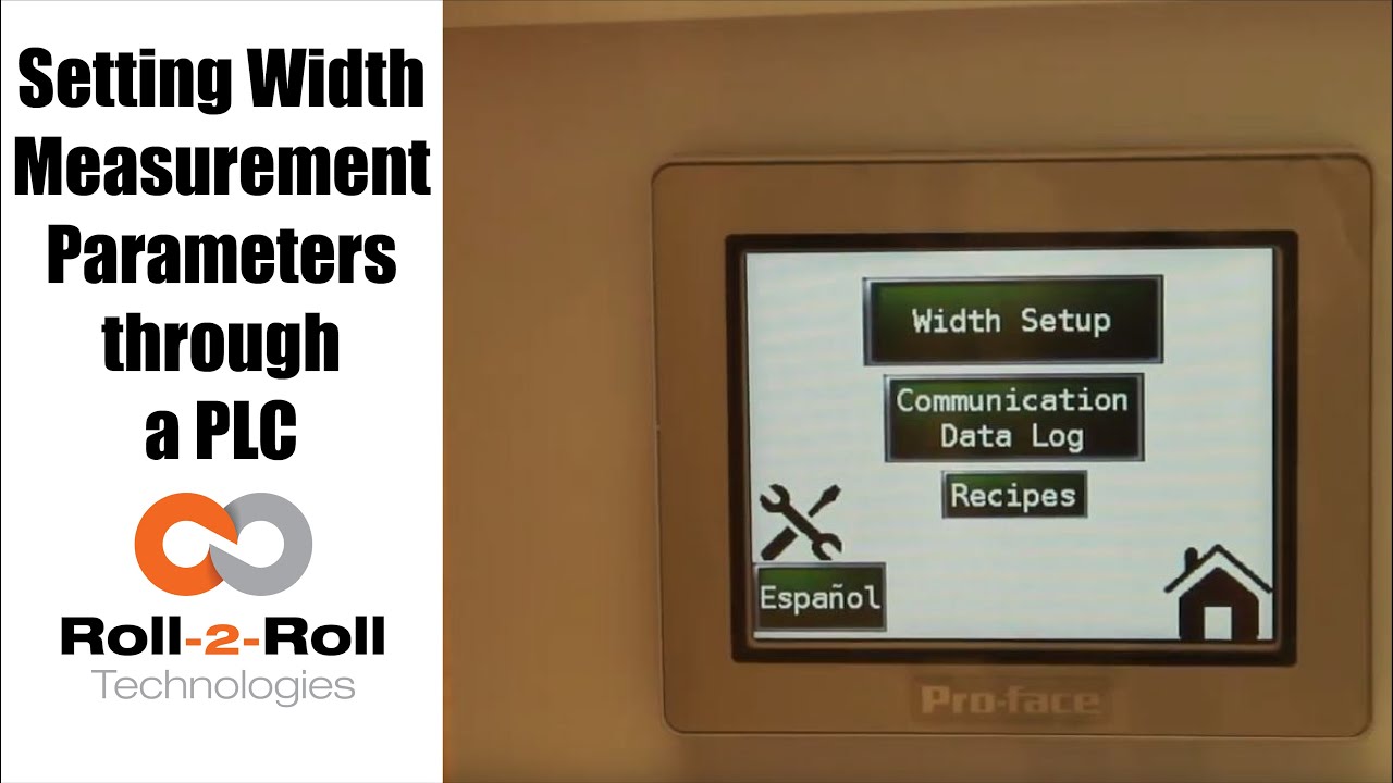
A programmable logic controller (PLC) or programmable controller is an industrial digital computer which has been ruggedized and adapted for the control of manufacturing processes, such as assembly lines, or robotic devices, or any activity that requires high reliability control and ease of programming and process fault diagnosis.
Transcript
Show full transcript (1078 words)
so in order to set up the Center for British Mint and we'll go over this menu once one more time we're going to go to the setup screen right here and then click on width setup then we can enter our nominal width the alarms the warning ranges and all those things first we want to whenever we have a new product in there we want to measure the product what the width of the product is in this case it's 153 millimeters we're going to enter 1 5 3 enter and then we're gonna set the warning to be point four millimeters so if the alarm is less than the warning the system will not accept it so the best way to do that is to make sure to set the alarm first so we'll set the alarm at 1 millimeter and there is a way for us to set a symmetric alarms so the positive range can be 1 millimeter and the negative range can be 0.5 millimeters if we want it to so in this case I'll set it at at 0.8 millimeters and then the warning range in this case let's set it to 0.4 millimeters and we have set everything what we want to do is to say hey this is the right one so we say record wait what it does is it teaches the sensor to say hey this is the nominal width we're looking for and I have presented the web with the right width and it'll take the measurement from then on so if you go back to the home screen it's going to show you the measurement and as long as it's within the range you're gonna have the green light whenever it goes to the warning limit it's gonna go to Amber and then whenever it's about the alarm it's gonna go to the red light these are actually also triggering a digital output on the PLC so we can connect a stack light with three outputs so connect the red sorry red amber and green to the three signals in the stack light the other thing that we want to point out a little bit more is the recipes so sometimes you might not see it you just have to click on this to say display recipe so what we have provided is an option for you to save seven different product recipes you can scroll through them and let's say we want to pick up product seven and we want to use that as the recipe what you need to first do is pick that number click on load and it's going to load the data here right now it doesn't have anything so let me go to one which has something ok so now I loaded product 1 and it had some values there so we'll have to load it once you load it it's loading is just for display purposes you need to press accept to accept that recipe so that it will be sent to the front screen for width measurement in this case I want to make sure to make some changes if you want to make the changes you can directly click on that width value and I'm going to enter 153 and then alarm as one date and then warning as 0.5 once I enter that if I press accept it's gonna send it to the front screen if you ever change a recipe you need to make sure to save it so right now I can press save now it saves it to the memory so that means that anytime you go back to that recipe and come back to one it will retrieve that data so make sure to remember to save it so two things one is if you want to load something it loads it here so we want to do that loads it here and if you want to take this recipe and put it into the front screen you need to press accept and any time you change the recipe you need to make sure to save it so that's the thing about recipes you have an option to say about seven recipes here there is also an option to log the data as you make the measurement there is a USB on this PLC so what you can do is you can connect a USB there and click on start logging it will it will start logging the data and whenever you're done you're gonna say stop logging and it'll stop logging the data and then you can take the USB off from there there are a few other settings here that you can set up as well these are advanced settings there is an option to override the minimum contrast in our sensor the minimum contrast is used to say whether something is an edge or not in the picture so by default we have 50 so we can have that and if you want to enforce that you need to press this button so that it changes into lime green instead of dark green whenever you want to disable you press that it disables that and this is the place where you can enter the value you can also make the sensor provide the data that is already filtered so if you want to do that you turn on the filter turn the lime green turn off the filter it goes off this is an advanced feature which is called as a minimum measurement quality whenever we take a measurement we have an output called quality factor and we can set that nominally it's ten millimeter ten is the minimum quality factor now if you want to make it higher you can set that value and enter it there so as long as there is a value it's going to take this value if you want to disable that option press n zero so I press ten and enter and it'll be that that's the minimum that you can provide so this screen is more like an advanced screen your operator wouldn't really have to do this only people engineers that are setting up the system can use this for troubleshooting purposes and stuff like that and yeah that's about it so these are the features there and like we talked about before we also have the option to log the data and showing the log of the data right here you
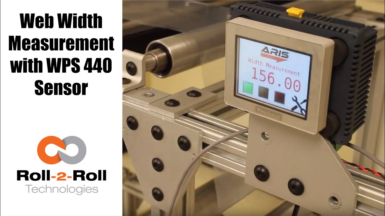
Roll-2-Roll Technologies offers robust width measurement capabilities with the WPS 440 Sensor. Using a PLC connected via ethernet, we are able to accurately measure the width of any material.
Transcript
Show full transcript (1727 words)
well today we just want to show a little bit more about our width measurement application with our 440 sensor so we have the 440 sensor installed and then you have the web coming over it we have installed two support rollers so that when the web moves it doesn't flutter too much we want to avoid fluttering whenever we do web width measurement this sensor is actually connected to Ethernet IP so you can connect it to a a PLC like this or we also have a web browser interface on the computer that you can connect to so the main things are here is how far the sensor is from the web right now we have installed it at about 5 millimeters from there that's the optimal distance that we recommend the sensor is installed facing up that is good but just to avoid any dust and other accumulation it may be better off to face the sensor down so that it's looking down towards the web a few other things that we need to consider is the the the free space behind the sensor we want to maintain about six inches of free space so that nothing in the background is seen by the sensor that's the optimal way in which we can get the best results there's also a way for us to get the maximum scattering out of the sensor if you want to do that what we would do is we will raise up this roller so that the web comes at an angle now about 10 15 to 20 degrees is the angle that we want and it depends upon the orientation of the sensor so if we if you want to get the maximum scrap scattering what we will do is we will raise up this roller so that the web comes this way but those are the few things that you want to consider before installing our 444 width measurement application other things to consider is this free span doesn't have any twisting so we don't want to install the sensor right next to a dancer roller or right next to a web guide we want to install the sensor between two fixed rollers so that we have a fixed pan and then web doesn't flutter that will be the ideal scenario what we were going to show right now is how do we get this up and running right now as you can see we have the power on to the sensor it's connected to Ethernet IP right now it's connected to a network device like a router or a switch so you can connect to the sensor through the network if you don't want to do that you can directly connect the sensor to the computer or you can directly connect this to your PLC or our PLC for that matter so just for demonstration purposes we're going to connect it to both the computer and the PLC to a network the next thing that we want to do is to connect the sensor to the PLC one of the first things that we want to do is find the IP address once the sensor is connected and powered up and connected to your network device we can pull up a utility called IP config we have information about that on our website we can go once you open up open up open up that program it will show what device there is and what's the IP address of that right now the device is said to have DHCP set automatically and it has an IP address 0 dot 0 dot 0 this is happening mainly because the Gateway doesn't match so what we would do is to make sure that they get the Gateway matches let's do that the Gateway is one one sixty eight dot one dot one and AP address of this device so right click configure on my parents one point something see you so once we do that we set a static IP address with the Gateway and everything now we can right-click and pull up a web browser and that's going to bring up our dashboard so this dashboard basically shows us several things the web measurement is shown here so this is the web in that the width measurement is 155 and something millimeters we also have a filtered width measurement we have a filtering algorithm that would take the filtered value of the raw measurement and then edge location which is left edge so that's saying where this edge is and then the right edge is showing where the other edge is and then within our software we also have what we call it as a quality factor which is basically think of it as how good of an image or how good of an edge that is so it says that the left edge has a quality factor of 300 and something and the right hand has a quality factor of 100 and something so this is a easy and quick and easy way to test our sensor make sure everything works fine we have a plot that shows the weight the measurement we also have other things that we can do with the sensor in terms of adjusting the brightness all of these are shown here so the idea the main thing that we want to do is make sure that the quality factor on the both edges are pretty high and as we mentioned before one of the things that improves the scattering is angling the sensor either we can lift this roller up or angle the sensor so that we get a pretty good quality factor so if you can notice when I move that since we don't get a good scattering the quality factor went down but if we install the sensor at the right about 15 degrees angle then we get a pretty good quality factor signal and then you get the measurement there so this particular web browser interface allows you to pan the data plot the data you can also save the data if you click on the save it stores that data as an excel file with all the information that we collect which is shown here such as the brightness and and the edge position and the width and everything so that's basically about the the web browser interface as you can see we can run the web and it collects the data as the web is moving over the sensor let's move on to the PLC and kind of show you how we can set up that PLC this is a special software that we install on it basically for customers who doesn't want to set up their own system they have the ability to use our PLC that we supply to do width measurement and also have the ability to provide a trigger measurement whenever the width varies so one of the first things that we want to do to get the PLC communicate with the sensor is to tell the PLC what the IP address of the sensor is in order to do that we're going to press these corners one after the other and then go to offline and this shows up the main screen here in the offline menu we click on peripheral and within the peripheral we're gonna select Device slash PLC setting and here we're going to use the ethernet/ip explicit messaging protocol so that's the one that we're going to select and then these settings are fine which is the standard setting the main thing that we want to set is the IP address of the device so we're going to go click on device and then set the IP address so right now it's set to 192 168 1 8 so our sensor IP address that we manually set was 192 168 1 dot 100 so we're gonna type in 100 enter and exit and then Save Changes so now the PLC is going to reboot with the new IP address we just have one more step to do to connect the PLC to the sensor or connect the PLC to communicate with the sensor and that's to enable the Ethernet communication so in order to do that we're gonna go into the settings and communication and turn on internet might be once we do that now we got the measurement from the sensor so this is the real-time width from the sensor that is going here now if the customer wants to set a few things for example if they want to teach the sensor so that we want to avoid any inaccuracy in accuracies in the measurement what we will do is we will put the web where at the location where they desire it and measure the width of the web then let's say in this case it's 155 millimetres would go in and press this 155 and press record width now they can also set warning and alarm ranges so for example we want to say alarm is for 4 millimeters warning is for 1 millimetre and going so as long as the width is within that range which is 155 we taught the sensor for that width it'll show green and whenever the width goes about a millimeter high or low the amber would show up and then when it goes about the warning the red would show up so and that's pretty much it right now we're seeing the weight variation because of the curls and all these things in the web we're trying to show or simulate some of the things that you would see when the weight varies by these curling there's also an ability for the customer to set recipes so if they have different product with you can set what is the nominal weight what is the alarm weight what is the warning with things like that you can load them you can save them and so on and so forth and also there's an ability to connect a USB here directly and save the data through the USB on this PLC right here and this PLC can be connected to an signal alarm signal lighting system with green amber and red so that it's readily visible for the operator running the machine so that's pretty much our width measurement system using our WPS 440 sensor you

Roll-2-Roll Technologies has released a new feature for it's web position sensors. This feature benefits all converting operations. The advanced contrasting capabilities can detect the smallest changes in colors and markings. Stay tuned for more information about our advanced contrast sensor capabilities for converting operations.
Transcript
Show full transcript (2108 words)
hi this is pivotal Velasco of roll-to-roll technologies today we're going to talk a little bit about our contrast sensing technology in how it works with our web guides you should typically some of our customers come to us a very very special situation they might say for example oh I want to guide this material but they really don't know how how to how can we get something that has gradients that you know that has no line in it well we have found a method of doing that we can guide based on it labels on the edges of labels we can guide based on features or contrast between colors and we'll talk a little bit about that we can even guide on labels that have irregular features as long as we can find something that we can guide through so today we're going to talk a little bit about what each one of these features how to go through our menu of applications for contrast sensing in web guiding applications so when you go to the screen you will see that there's a tool icon right there let's press on that tool icon that tool icon was tickets to another screen where you can see that we're on the sense sensing mode right let's hit the tool icon on top again and then we get the different this is the the screen where you will get all the different options for doing the contrast sensing in this case when it's red it means that it's already set on a specific application so now what we're gonna do is let's see all the different applications you can do by hitting on that icon there it will turn green and it'll show all the different applications now right now it's showing what we consider to be the most robust application that is it's actually seeing the border of both borders of a specific contrast in this case it can be a single color but it's actually working on two principles one it's the color and the second is the width that of that line or that color so as long as it sees that it will continue to guide or follow that based on that that is the most robust application we have for contrast sensing however the next most robust applications are actually the two on the end in this case when we hit it there it just means that it's going to look in a contrast on on a color that it's represented right now but this orange bar but it's looking and where that contrast begins from this side right and on the other side does the opposite right so in a second we'll see all these applications in working right and the least robust but it's still very useful is this one where it actually looks at to contrast and and then it looks at where those two countries are actually occurred okay so once we select that we can actually go with these two icons on top we can actually select which one of those in a specific contrast setting we can which one we will select and we'll show that in a little while when we do our applications so if I want to just set I just hit this icon again and now it's on the on this application which is looking at the other line that is caused by two different contrasts in there right and then I just hit back on the home button and takes me back to the original screen so I'm not going to show you different applications with some materials that I have here so for example we can have an application where we have labels printed on a material but you can see the labels only have this permanent edge and on this side it has an irregular feature so one application that we can do is we can actually tell the the system to look for this edge right here now this is one of the most interesting features of our sensors even though these are different colors and ingredients we can still guide on this line right here and even though there's a break in between there's a special condition in our in our in our system where what it will do is if it's in a guiding mode as soon as it sees this this break it will actually lock the position of the web guide at that and then once it sees it the the contrast again then it will go back to guiding mode so of course if this is moving really fast it actually you can't really see when the web guide stops when the locks in place because it just keeps on okay that's one application another application we'll talk about it's this one see in this case we have something similar but but we can actually we have several options to guide from we can actually guide with this in the middle and we can use the most robust application which is actually saying this is a bar right down the middle even though you see that there's a gradient there because of a way our sensors and controls are made that technology that we have it actually looks at this as if this was a line of a constant width so we'll see that application there and of course when we're talking about the lines just the least robust but it has a very good application in the case like this where you have orange and black so we might want to guide on this transition between orange and black okay and we will look at that in a second as we do each one of these applications so let's work with this application in particular so in this case we have an irregular feature on one side but we do have a feature that is constant it's just that there's there's a constant line that we can we can call it a line and the width between here is also constant but we can guide on this feature right here right now which is the edge of all these labels right remember what I mentioned before if there's a break the web guide would lock in position until it sees that material gate and it doesn't care really if the cont if the color changes all it's looking for is this edge right here so if I position the material right here on our on our sensor one thing that we'll do is first let's go back in the in the in the system and let's go into the tool mode and go all the way back I have already pre-selected but let's say that we were here we can actually do and select this one right here which is the one that we like it's looking from this side to this to the edge right and then I can tell it here by moving right now it's actually looking at the black surface up to the edge where it starts with white but I don't want a guy there I want a guide on the white on this edge right here so I can move it the position right there and I can tell it lock it there and now it is locked and then I go back in my home program and as you can see you see this is the black material on the back this is the black material on the back this one here is this white up to the edge of the label and this is the label but as I move it let's put it right here and say it's in the center and as I move it you'll see that once it loses the contrast it will lock in position you see it keeps it all the way through I mean and that's what I'm looking for and you'll see a green line which actually tells you in this case it's actually looking at the place where this white between the labels and it has locked in position there so no matter what I do as long as I keep it there you see that the green the green line stays but as soon as I move it it picks it back up again now let's look at this application in this case we see that the best way of guiding with this material would be looking at what is constant the only constant we have here that we're sure of is that the width between this this a feature here or this label and in the other label so it creates kind of like we're gonna call it like a white line even though it's has gradients right however the width is constant throughout so we're gonna work on that one place the material right here and then we're gonna go into our menu and then we're gonna select the appropriate feature that we want so we're gonna do the one in the middle remember I told you one before that it is the most robust feature there is however I do have to pick which one I'm looking at I know it's this one and right in the middle which is the white space between the two labels so I can select it right there and then I say let's pick that and it is set when I go back to my main menu as you can see the green says that is right in the middle and as I move it around you see how it follows the material based on that but notice that when it loses it it locks in position until it finds it again that is one of the main features of our system now in this case we want to do something very interesting we might have a feature which is kind of hard to detect in this case we have orange and black we want a guy by the line that is created between that transition from orange and black so what we do is we go back in our menu right and then we pick which one we want and we're going to pick this one right here now here's something very interesting once we I have picked it I can also say I can have to I have to select it right through here so what I know is right now the transition this bar right here is the orange this is the black this is the white and I can move it around I can say pick on this one or pick on that one ring but I want to do this one which is a transition as you'll see you'll see a green light or a green line that goes around the two features right and it's going to be right in the middle there where the transition occurs because I picked that one which is right in the middle here I can go back in my menu and you can see right there where the Green Line is right where the black and orange meet right now what is a special that this feature is that it will only look at where orange and black comes in that arrangement Orange on this side black on that side you know we'll just follow that feature through me and if it loses it like before it just locks in the last position but then when it's picked it back up he keeps alone now I have another orange in black but if I put that one there see it's not gonna pick it up it's not on the right orientation right so that is one of the features another feature that we have with this so we hope that this information is of value to you we know it should be we're really interested in knowing any other applications you might think of however think of this we have a web guiding technology that uses contrast sensing that can handle very difficult applications where where the contrast has really has some some very specific features such as gradients maybe irregular features as long as we can find something where we can guy from we can provide you a good guiding system based on contrast you can see more of this in other features that we have in our in our products by visiting our website which is WWF tag team thank you you

Roll-2-Roll Technologies shows just how easy it to set up its web guiding system. The automatic function does all the work, so you don't have to. Just press the automatic button and let it roll.
Transcript
Show full transcript (248 words)
As a real plug-and-play system, ARIS adapts to any material, requires no calibration, and very little set-up time. First plug in the sensor to the 12 prong outlet in the back of the machine, using the guide notch that aligns the plug to the outlet. Once the sensor is plugged in, tighten the lock collar to hold the sensor cord in place. Slide the sensor into the sensor guide rail.
Make sure the middle of the sensor is aligned with the material’s edge. Once connected to a 24 volt power supply, the user operator interface featuring language independent icons will come. A green sensor indicator will verify an operable sensor. Above the icons you will see the material edge, position indicator, represented by a green and red bars.
When the material is in correct position, you will see one red bar and one green bar. If it's incorrectly placed, you will either see no green bar or red bars on both sides of the green. Once the sensor has been aligned with web, secure the sensor using the thumb screws. When the screen turns on, the automatic/manual icon will indicating the guides last operating condition.
A green icon indicates the guide is in automatic operation. A red icon indicates the guide is in manual operation. The operator can change the condition by pressing the icon once. ARIS does most of the work through its automatic option, so press the icon to set to green and let it roll.

Just received the latest web guiding technology? Check these unpacking instructions before you get started!
Transcript
Show full transcript (203 words)
The ARIS web guiding system will arrive packaged in a cardboard enclosure specially designed for the web guide. Make sure you open the box in the upright position. The upright position can be verified by printing on the outside of the box. The packaging must will be enclosed in a clear pouch on the top of the box.
Use the packaging list to verify the items received. The package will include a product shipping sheet with technical information of the product and links to get online access to the product manual and technical support. Although the packaging is designed to protect the product from shock due to transportation care should be taken and handle in the box with the guide to avoid damaging the device. The sensor is shipped uninstalled from the guide at unit and will be packaged within the protective cardboard enclosures.
The cardboard enclosure is accessible after the web guide is removed from the box. Remove the protective cardboard enclosures carefully to avoid dropping the sensor assembly and remove the sensor from within the cardboard enclosure. The optional pre-wired power adapter will be packaged in the same cardboard enclosure assembly as a sensor unit if the order includes this option.

We are often asked how to calibrate our sensors. This video will show that you don't need to calibrate our sensor.
Transcript
Show full transcript (387 words)
Hi, this is Pedro Velasco with Roll-2-Roll Technologies We want to answer one of the questions that reader in e-news sent us. His question was literally just how do you calibrate your sensors and one of the things we do with Roll-2-Roll Technologies with what we have developed It's that you have to, you don't need to do any calibration of our sensors. Right here today I'm going to do a very short demo using one of our demo units plus two of our main sensors, the 48 millimeters White light sensor to use for contrast sensing and edge sensing and then our white 221 millimeter sensors infrared which we use for edge detection but also for measuring width and center guiding. So let us show you how.
In this case you notice immediately as soon as I plug it in the sensor came on with no need of any other procedure in just coming you know. Now as you can see right now on the screen the sensor I have to go and tell it find the sensor It's searching and then as soon as I put the material It detects where the sensor is at. As you can see it's actually detecting the material as it goes through Ok so now let's say that I want to change the sensor for some other reason and now all [I] do is just unplug the sensor And as soon as I unplug it the display tells us that there's no sensor there and at the same time I'm going to plug in one of our featured sensors the 221 millimeter sensor which has many capabilities like for example We can do edge detection, it can do width sensing and immediately it detects a sensor there. However I'm going to do a search sensor and the same procedure and as soon as I put material it detects the material.
Now it is only guiding off on the edge of the material on the leading edge. That is how simple it is Change Sensors and as you can see there's no need for calibration We hope that this video has helped you understand a little bit more about our about our technology And we will continue to show more stuff, but especially the features that are sensors have. Thank you.

Do you need to find the IP Address of the SCU5 controller? See our video to learn how the IP address can be found.
Transcript
Show full transcript (541 words)
Hi this is Pedro Velasco from Roll-2-Roll Technologies. Today we want to show you how to find the IP address for ARIS sensors or web guide controls are equipped with the Ethernet IP connectivity option. As an example today we're going to use the WPS 440 IR which is a most recent additions to the ARIS WPS sensor lines and this one has an inner router to access the network so that we can monitor this later on. So first we're going to connect an ethernet cable to the M12 connector which is on the side port of the ARIS the WPS 440 IR and then the other side of the connector we're going to connect it to the router in the rj45 Ethernet connector jack Once it is connected, then we go ahead and connect the power to the sensor and then we verify that the connection is correct by looking at the blinking light on the router.
Now after this has been achieved then we can go ahead and proceed to a computer to actually go and find out the IP address for this particular sensor. So by default the router will assign an IP address to the device and this will be a dynamic IP address. Now to find the address you will need to access the Internet through any computer from which you will monitor the device in this case we searched online for Anybus.com and then we look at the support so we hit the support tab. Then we go to the selected product icon and from the select your product Icon you go to the Anybus IC icon and you click on it.
Then you go to the Ethernet IP and here you have a list of software so you're going to download on the software section when the one that says IP configuration utility for module TCP IP configuration. Now you go through the whole process of downloading the this software but once you download then you hit your Start button on your screen and just go to the HMS as you see here and open that up and then you see the IP configuration. When you click on it, it will automatically open this this window right here. Of course, sometimes when you're doing the first time this will not show up so you hit scan and it will scan for anything, any IP addresses are available.
So in this case here you have access to your IP address. Ok, so let's say for example you want, this is a dynamic address, but you want to establish a static address so all you have to do is just right click on the on the line and then you see the configuration tab. Just hit configuration and then you can actually set your static IP address on this window right here. So we mentioned before how to find an IP address for one of our sensors or web guide controls.
It's a very simple procedure as we showed and we hope that this can be of help to you when you are using our products on your operations so again thank you very much and just keep on looking for other videos. Thank you

Check out our newest feature in web guide controls for our web guides, which allows you to change the guide point without touching the sensor!
Transcript
Show full transcript (241 words)
Today we want to show a feature in our web guides that allows for guide point adjustment We can do a fine guide point adjustment or a gross guide point adjustment without having to physically move the sensor The adjustment can be made on the operator interface by just sliding our finger across the screen In a previous video we talked about the fine guide point adjustment and today we want to go over the gross point adjustment For that we have to go to the operator interface screen, and there is a black bar on the screen and all you have to do is slide your finger across the black bar and it will move the guide point After that you will need to hit accept and the guide point will be set Unless you hit the accept button after moving the guide point, the system will not register the change in guide point If by mistake you touch the screen and move the guide point, the guide point will return to its original setting unless you hit the accept icon This is just another of our features on our web guides available in the control unit version 2.4 which is standard in all our web guides since June 2017 Fine and gross guide point adjustment, something we believe will be very beneficial for any converting operation Visit our website at www.r2r-tech.com for more information on all these features