Resetting the Guide Point in Center Guiding with SCU6x Controller
This video explains how to reset the Guide Point in Center Guiding using the SCU6x Controller. It demonstrates the process of center guiding with two sensors and showcases how to reset the guide point and adjust the offset. You'll learn how to manage the actuator direction changes and understand the reasons for allowing a guide point offset even when aiming for center alignment.
Transcript
Show full transcript (209 words)
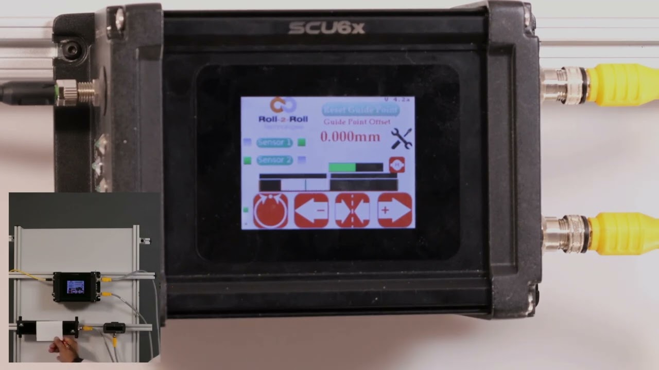
One of the other things that I want to show with center guiding is that you can do the reset guide point just like what we did with edge or center guiding with two sensors. Let me show you that. Going back to the screen here, we have the web now and the green position indicates the center line position. If the web is moved that way and for whatever reason you need to do that, you could do the same reset guide point and accept.
Now the guide point offset is there. If the edge position goes on either side, the actuator changes its direction back and forth. This is for doing the center guiding with the point offset. Now, like I said, it's not usable for you to change the guide point offset with center guiding just because you want the material to be aligned to the middle of the machine.
The reason why we allow you to do that is that let's say you had not installed the sensor at the right location to begin with. Instead of going and physically moving the sensor, you could just move the offset. And that's the reason why we allow a guidepoint offset even when we do center guide.
This video looks at protecting access to the operator and power user screens through the use of password protection in the SCU6x Controller. It shows how to enable and disable the password, explains the different user levels, and how to change the passwords. The video also covers important information about default passwords and the process to reset them if forgotten. Operator Screen Access Protection.
Transcript
Show full transcript (556 words)
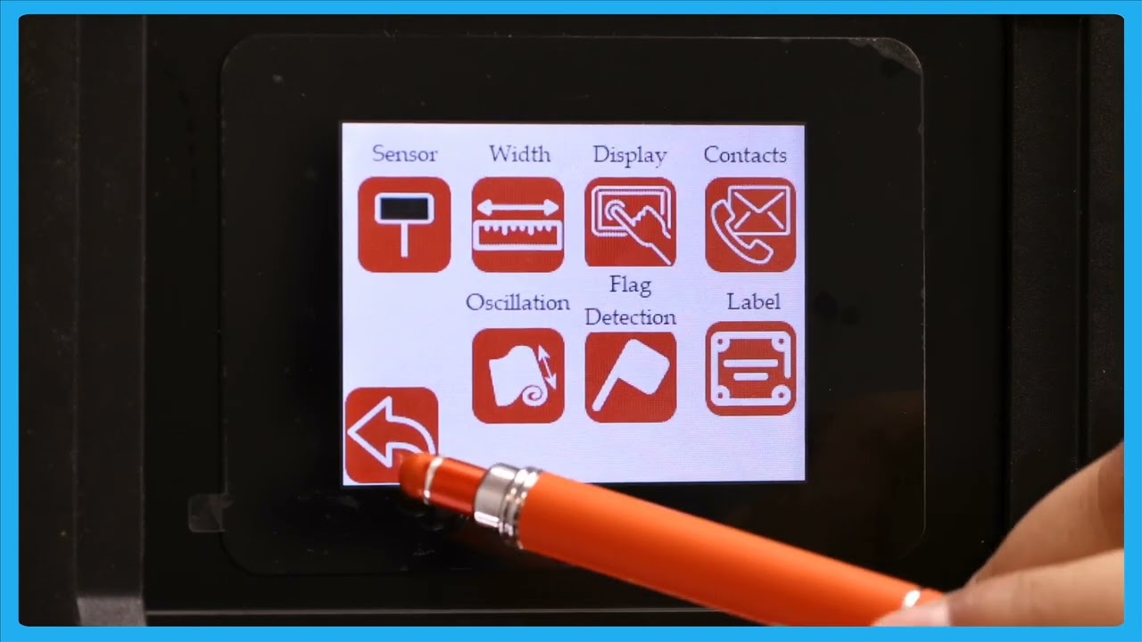
We talked about this tools icon here and one of the common questions that we get asked is is it possible for us to lock the screen so that only people who have privileges to access that have access to it and we can do that in our password screen right here. This password screen allows the operator or the power user to lock certain parts of the controller so that the access is restricted to those who are familiar and knowledgeable about what the consequences of the changes would be. So there are two main user levels. This one on the top is what we call as an operator level axis.
This would be any operator that needs to change certain things with respect to the controller including setting up the sensor. If you want to do line guiding, contrast guiding or pattern guiding, all of those are available to the operator through the operator screen. If I click on that, you can see the things available for the operators to change. Again, setting up the sensor.
If you're doing width measurement, you can look at the different width measurement options that we have. We'll go into detail about this in a later video. And then the next level of access we have is the power user. This is somebody like a maintenance professional or anybody involved in commissioning our system.
Most of the functionalities here are one-time kind of things that you need to do when you try to install the system for the first time. So again a setting related to the actuator some other high-level sensor related settings controller options and communication if the customer wants us to enable or disable certain access levels we can do that and that's available in the power user to be able to do it. One of the questions that we get asked all the time is how do you know when a password is enabled or not? As long as you see these icons, that means that the passwords are not enabled.
If I go in and enable the password on the operator screen, then that icon has disappeared. So, you won't be able to have access to that unless you enter the operator password. Likewise, if I go in and lock the power user screen, we won't be able to see the the icon for that. Nobody would be able to enter it unless you enter the password.
That's essentially how you would enable and disable the password. [Music] If you want to change the password, there's an option to change the password. All you need to do is pick the password you want to change. Let's say the operator or the power user.
You would click that, enter your current password, and then change it to new password. So, the passwords are fourdigit long. and please contact the factory to get the default password information. Once you have the default password, you can go in and change the password for the operator screen and the power user screen.
But please note that once you change the password, there's no way that we would know what the password is. So, we wouldn't be able to recover that unless you send the controller back to us. So, that's essentially what this password screen is. [Music]
In this video, we explore the nuances of using different sized sensors for center guiding in web applications with the SCU6x Controller. Normally, it’s recommended to use two sensors with the same measuring range and resolution to avoid confusion. However, this video demonstrates how it's possible to use sensors of varying sizes and addresses the potential confusion that may arise. You'll learn about sensor configuration, including how the screen displays information when different sensors are used, and how the web position indicator operates.
Transcript
Show full transcript (363 words)
one of the things that I want to point out is that in uh normal situations we will always ask that uh when you do Center guiding with two sensors that you use two of the same sensors with the same measuring range and same resolution it just makes it easy and it avoids any confusion here I just wanted to show that it's possible to use different sizes of sensors when you do centering uh what where does this confusion come from just to show on the screen what I mean by that we have one sensor configur to left and the other sensor configur to the right and when we do that the screen is going to be split up into two regions or the web position indicator is going to be split up into two regions if I present the web on just one sensor so I'm presenting it on sensor one which is config as great sensor you can see that only that great half is being updated likewise only the left half is being updated and then when I have a web wide enough it sees both sensors then the portion of the left half corresponding to the left sensor and the portion of the right half corresponding to the right sensor is only going to show up there so the confusion arises mainly because we have one sensor that is almost six times or or eight times wider than this sensor but we only have the same 50% uwing area on the top so when we move just a little bit on the bottom sensor it seems like it's moving a lot whereas when we move little bit on the top the the right left sensor then it seems like it's moving a little but in reality it's moving the same amount but it's just that on the screen we don't have we're not scaling that based on the two different sensors range so that's the difference so we covered the main things with the sensors in terms of the orientation how the web position is indicated how you get the web detect signal and things like that
Transcript
Show full transcript (356 words)
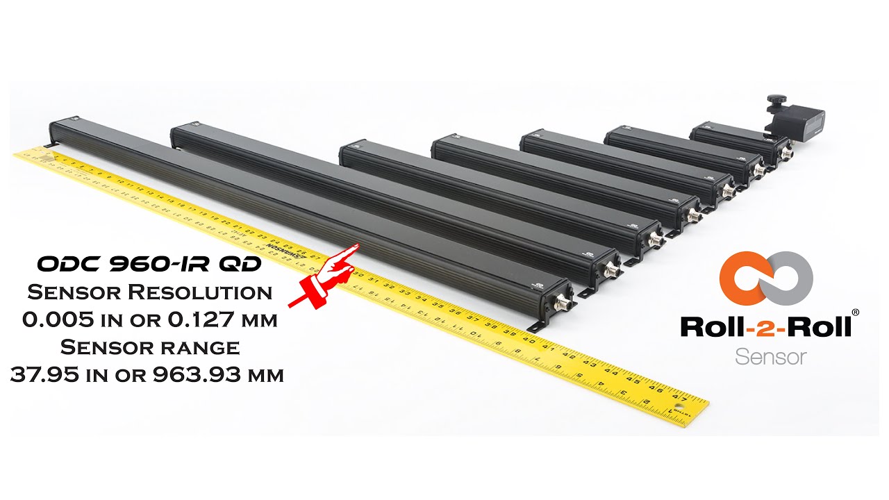
Hello everyone, this is Aravind Seshadri from Roll-2-Roll Technologies. Today we are really excited to talk about one of our newer products for edge guiding, sensing and different applications. We have our ODC 960 this is one of the widest edge sensor that is available in the resolution of 5 thousand's of an inch and this is one of the higher resolution cameras that we have for such a wide sensing range. There are lots of applications for this including web guiding, width measurement, thread counting, flag detection, splice detection.
Some of the unique features of this system is that it is a one sided solution. So when you have a one sided solution you don't have issues when you are trying to install it in a compact space. Becasue if it is one sided you can install it vertically or you can install it facing down so that you don't have to worry about the dust accumulation on the sensor. It also occupies a This is an unique and proprietary technology where we have our linear optics.
This allows us to install the sensor really close to the web. So even though the field of view is pretty wide. You don't have to worry about trying to have a large working distance. We don't have that issue.
And also because we have the linear optics we have a 1:1 magnification ratio. That means that we have a really good resolution in terms of the image that we are capturing. If you compare that to traditional machine vision system with a circular optics, when you increase the field of view your resolution goes down. In our case our resolution doesn't go down.
Right now we have plugged it up with our SCU5 controller where you can get about 5 thousands of an inch resolution. This can be used any of the applications we already support. Anyway we are introducing this at the converters expo show 2023 in Greenbay. And it should be available this summer for purchase.
Take a look at our website and we will have more information about the sensor and feel free to contact us. Thank you!
Roll-2-Roll Technologies would be introducing the WPS 900 sensor, one of the widest sensors that in the market. With over 35 inches of sensor range, this is one of the widest edge sensors, if not the widest in the converting industry. Please come visit us at the booth to find out more.

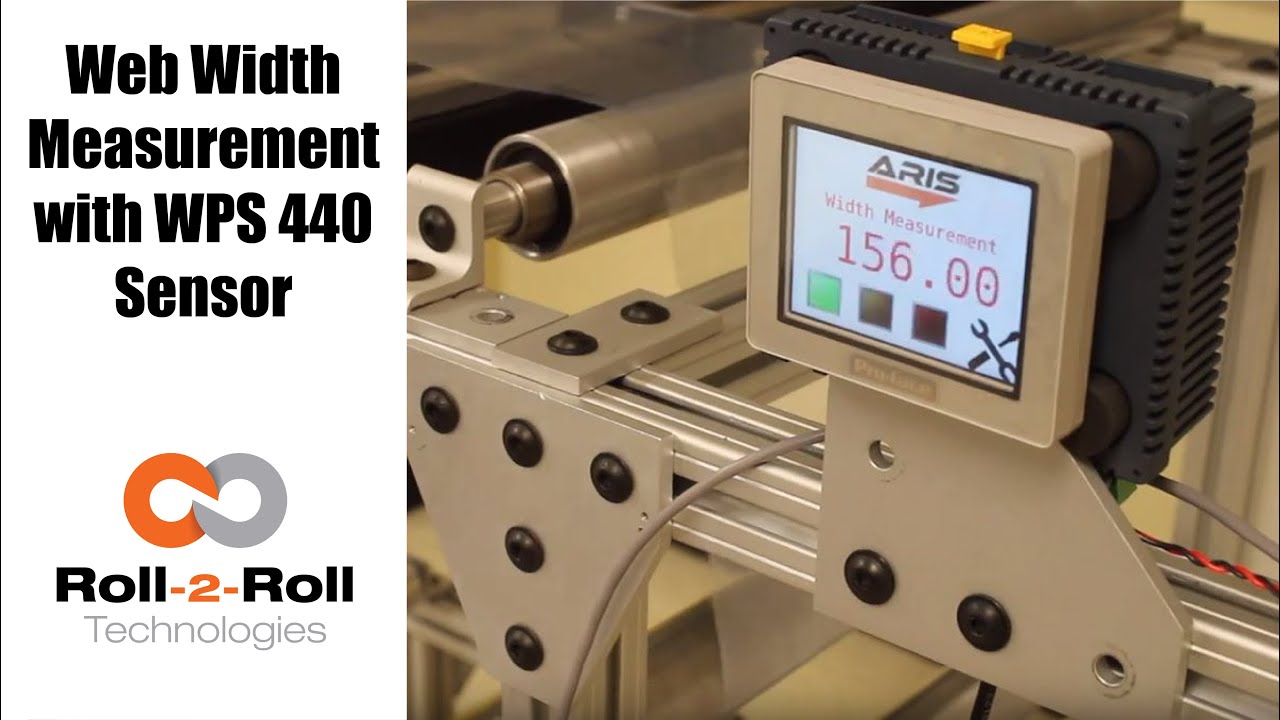
Roll-2-Roll Technologies offers robust width measurement capabilities with the WPS 440 Sensor. Using a PLC connected via ethernet, we are able to accurately measure the width of any material.
Transcript
Show full transcript (1727 words)
well today we just want to show a little bit more about our width measurement application with our 440 sensor so we have the 440 sensor installed and then you have the web coming over it we have installed two support rollers so that when the web moves it doesn't flutter too much we want to avoid fluttering whenever we do web width measurement this sensor is actually connected to Ethernet IP so you can connect it to a a PLC like this or we also have a web browser interface on the computer that you can connect to so the main things are here is how far the sensor is from the web right now we have installed it at about 5 millimeters from there that's the optimal distance that we recommend the sensor is installed facing up that is good but just to avoid any dust and other accumulation it may be better off to face the sensor down so that it's looking down towards the web a few other things that we need to consider is the the the free space behind the sensor we want to maintain about six inches of free space so that nothing in the background is seen by the sensor that's the optimal way in which we can get the best results there's also a way for us to get the maximum scattering out of the sensor if you want to do that what we would do is we will raise up this roller so that the web comes at an angle now about 10 15 to 20 degrees is the angle that we want and it depends upon the orientation of the sensor so if we if you want to get the maximum scrap scattering what we will do is we will raise up this roller so that the web comes this way but those are the few things that you want to consider before installing our 444 width measurement application other things to consider is this free span doesn't have any twisting so we don't want to install the sensor right next to a dancer roller or right next to a web guide we want to install the sensor between two fixed rollers so that we have a fixed pan and then web doesn't flutter that will be the ideal scenario what we were going to show right now is how do we get this up and running right now as you can see we have the power on to the sensor it's connected to Ethernet IP right now it's connected to a network device like a router or a switch so you can connect to the sensor through the network if you don't want to do that you can directly connect the sensor to the computer or you can directly connect this to your PLC or our PLC for that matter so just for demonstration purposes we're going to connect it to both the computer and the PLC to a network the next thing that we want to do is to connect the sensor to the PLC one of the first things that we want to do is find the IP address once the sensor is connected and powered up and connected to your network device we can pull up a utility called IP config we have information about that on our website we can go once you open up open up open up that program it will show what device there is and what's the IP address of that right now the device is said to have DHCP set automatically and it has an IP address 0 dot 0 dot 0 this is happening mainly because the Gateway doesn't match so what we would do is to make sure that they get the Gateway matches let's do that the Gateway is one one sixty eight dot one dot one and AP address of this device so right click configure on my parents one point something see you so once we do that we set a static IP address with the Gateway and everything now we can right-click and pull up a web browser and that's going to bring up our dashboard so this dashboard basically shows us several things the web measurement is shown here so this is the web in that the width measurement is 155 and something millimeters we also have a filtered width measurement we have a filtering algorithm that would take the filtered value of the raw measurement and then edge location which is left edge so that's saying where this edge is and then the right edge is showing where the other edge is and then within our software we also have what we call it as a quality factor which is basically think of it as how good of an image or how good of an edge that is so it says that the left edge has a quality factor of 300 and something and the right hand has a quality factor of 100 and something so this is a easy and quick and easy way to test our sensor make sure everything works fine we have a plot that shows the weight the measurement we also have other things that we can do with the sensor in terms of adjusting the brightness all of these are shown here so the idea the main thing that we want to do is make sure that the quality factor on the both edges are pretty high and as we mentioned before one of the things that improves the scattering is angling the sensor either we can lift this roller up or angle the sensor so that we get a pretty good quality factor so if you can notice when I move that since we don't get a good scattering the quality factor went down but if we install the sensor at the right about 15 degrees angle then we get a pretty good quality factor signal and then you get the measurement there so this particular web browser interface allows you to pan the data plot the data you can also save the data if you click on the save it stores that data as an excel file with all the information that we collect which is shown here such as the brightness and and the edge position and the width and everything so that's basically about the the web browser interface as you can see we can run the web and it collects the data as the web is moving over the sensor let's move on to the PLC and kind of show you how we can set up that PLC this is a special software that we install on it basically for customers who doesn't want to set up their own system they have the ability to use our PLC that we supply to do width measurement and also have the ability to provide a trigger measurement whenever the width varies so one of the first things that we want to do to get the PLC communicate with the sensor is to tell the PLC what the IP address of the sensor is in order to do that we're going to press these corners one after the other and then go to offline and this shows up the main screen here in the offline menu we click on peripheral and within the peripheral we're gonna select Device slash PLC setting and here we're going to use the ethernet/ip explicit messaging protocol so that's the one that we're going to select and then these settings are fine which is the standard setting the main thing that we want to set is the IP address of the device so we're going to go click on device and then set the IP address so right now it's set to 192 168 1 8 so our sensor IP address that we manually set was 192 168 1 dot 100 so we're gonna type in 100 enter and exit and then Save Changes so now the PLC is going to reboot with the new IP address we just have one more step to do to connect the PLC to the sensor or connect the PLC to communicate with the sensor and that's to enable the Ethernet communication so in order to do that we're gonna go into the settings and communication and turn on internet might be once we do that now we got the measurement from the sensor so this is the real-time width from the sensor that is going here now if the customer wants to set a few things for example if they want to teach the sensor so that we want to avoid any inaccuracy in accuracies in the measurement what we will do is we will put the web where at the location where they desire it and measure the width of the web then let's say in this case it's 155 millimetres would go in and press this 155 and press record width now they can also set warning and alarm ranges so for example we want to say alarm is for 4 millimeters warning is for 1 millimetre and going so as long as the width is within that range which is 155 we taught the sensor for that width it'll show green and whenever the width goes about a millimeter high or low the amber would show up and then when it goes about the warning the red would show up so and that's pretty much it right now we're seeing the weight variation because of the curls and all these things in the web we're trying to show or simulate some of the things that you would see when the weight varies by these curling there's also an ability for the customer to set recipes so if they have different product with you can set what is the nominal weight what is the alarm weight what is the warning with things like that you can load them you can save them and so on and so forth and also there's an ability to connect a USB here directly and save the data through the USB on this PLC right here and this PLC can be connected to an signal alarm signal lighting system with green amber and red so that it's readily visible for the operator running the machine so that's pretty much our width measurement system using our WPS 440 sensor you
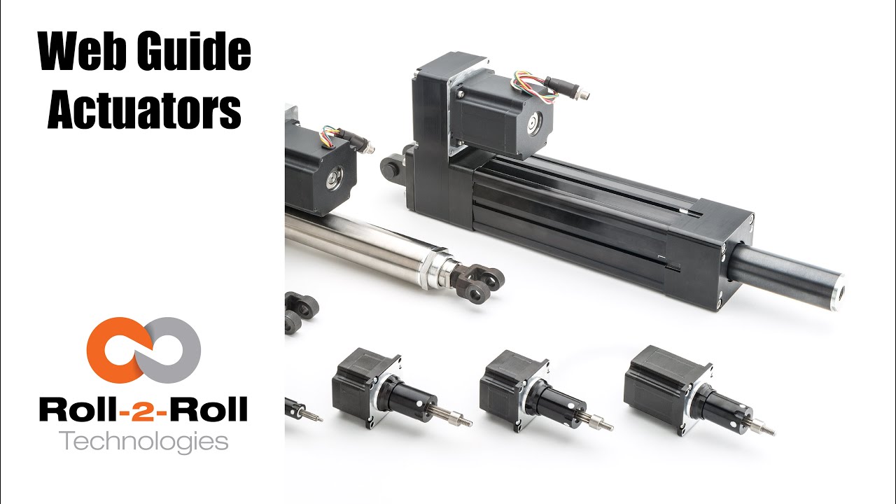
Roll-2-Roll Technologies doesn't just cater to the narrow web guide applications. Our line of actuators can help you in both narrow and wide web applications at any point in your converting process that requires accurate and precise positioning of your web.
Electromechanical actuators are used when quick reactions to changes in the web position are needed. The actuator connects directly to the control unit.
Transcript
Show full transcript (657 words)
hi this is petrol in law school with roll-to-roll technologies most people think of us as a narrow web company but we actually go into the white web applications - and to show you that we want to present to you our wide range of actuators available for both narrow web applications and white web applications in this front row I have for our narrow web applications these are the actuators that we use in our smaller web guys they go up to about for up to 22 inches in width and so they can handle web's up to 20 inches in this case this a small actuator is what we use it can handle up to 50 pounds of thrust so 450 pound tension applications and it's what we use in our low profile web guides then we have our our larger actuators which we use for applications such as our compact web guide and these can also go up to 50 up to about 150 pounds of tension and then we have the double stack actuator which we use in bigger applications and these can go up to 200 pounds force so they're all available for you for narrow web applications also we have an application for our retrofit kits in this case I have one of our featured actuators which you can see it also has mounted the several Center on it now this is a very robust application it can be provided with you with eyebolt terminals on either side or we can easily with clevis doing so if you have a web guide in your in your plant that requires you know the mechanical parts are all good the controls are update outdated you can actually we can provide you with an actuator and our controls and sensors to it so this is more or less the setup that we will probably we can mount it either through the eye bolts we can mount it through clevis or we can mount it directly on a any fitting that you might have on your machine these are very easy to install and they come already with the several Center mounted on them so it's all up to the particular application that you have in a problem that you want to solve another area that we want to talk to you about is on our terminal web guides like I mentioned before people think of us as a narrow web company but we're not we actually cater up to also the the wide web applications and also we cater to the terminal guy diplucate so in this case we have featured some of our what we call the actuators for terminal guides for online xandrie once we have multiple ways of installing these on your machines depending on your needs we can do either clevis mountings or we can install it directly on the base of the actuator now we can provide you one that would work that would move a 1500 pound load a 5,000 pound load or up to 15,000 pound load so it's a very hefty product as you can see it's a very heavy and we use it to like I mentioned before to move unwinds and rewind so I have it hooked up to our one of our control units with one of our infrared sensors and just to show you how easy it is it can work pretty well with our with our controls right here right and if I put it on automatic as I use my hand as a material you see how it just and we can adjust the speed of this application depending on your needs so we hope this has been of information of use to you and like I mentioned before if you need any help with retrofitting an old web guide you can contact us more information you can go to our website ww2 and thank you for a time you
Transcript
Show full transcript (415 words)
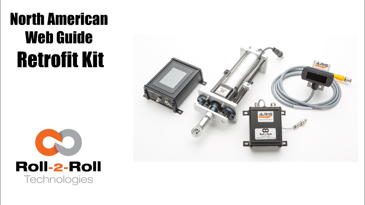
alright this is better with law school rolls roll technologies we want to show you one of our applications which is retrofitting old web guides in this case we have a North American and we just want to show you really quick how you know the things that we do in order to retrofit one of the North American web guides with our controller in with our actuator and sensor so here we're showing you the assembly as we have already done the retrofit of the actuator to the web cat assembly which moves the top plate where the rollers are at as you can see here's our actuator with its a threaded rod and it's already connected to the raceway here so we have actually replaced already the rest of the components of this and the previous secretary that it had so it's a very very simple application and we provide the plates and we provide the actuator and of course we have it connected to a motor driver this is a temporary murmur of driver just for the sake of this presentation so a complete retrofit for doing this case for this guide would be the actuator which is motor driver our control unit and a sensor which depending on the application that our customer has it could be a forty eight millimeter sensor or it could be a two hundred twenty one millimeter sensor so right now just to show you more or less the final application or all the connections already completed we're just going to show you that we can jog already with our control we can jog our our motor in position furthermore if I just place my hand to use as a material a possible material I'll just put it in automatic and you can see how moves the whole thing so there you go it's a pretty easy setup for us so if you have an old web guide such as a North American and you want to do a retrofit this is what we can provide you with a retrofit kit you can either install it or in some cases you can send us a web guide to us and we can do the retrofit for you so we hope this has been of information of use to you and like I'm in before if you need any help with retrofitting an old web guide you can contact us more information you can go to our

The Pneumohydraulic Replacement Kit from Roll-2-Roll Technologies comes complete with Cylinder Replacements. We've adapted these cylinders, so they can just drop into the pneumohydraulic machines. Learn more about Pneumohydraulic Replacement Kits at https://r2r.tech/products/web-guide-replacement-kit
Transcript
Show full transcript (162 words)
so one of the important features when we're doing a pneumo hydraulic retrofit is the replacement of the hydraulic cylinder and in this case we do that replace with one of our linear hyper actuators and we have actually prepared them in such a way that you can use them as a drop-in in place of the hydraulic cylinder now one of the main features is we can do it for any size as long as we have the dimensions that you want to do it that you want to put your the actual area in but at the same time we provided with two types of brackets on the on the back end and I bracket or you can have a closed bracket on the back end and of course on the rod end we would have a closed bracket so this is one way you can easily replace the hydraulic cylinder on your retrofit of the pneumo hydraulic system you