
April 11, 2018
Looking for a way to update your pneumohydraulic converting machine? Using a retrofit kit from Roll-2-Roll Technologies saves money and hassle without having to replace your entire line. Learn about the many benefits a web guide retrofit kit has to offer. Whether you want to upgrade an existing machine or experience the latest in web guiding technology on a smaller budget, retrofit kits are the answer.
Transcript
Show full transcript (960 words)
hello this is peridot a last go with roll-to-roll technologies now we have customers that have come to us because they have new more hydraulic units installed on their own their lives now they're using this new hydraulic units to guide the web now there's something a problem with these new hydraulics is that number one there are very bulky piece of equipment so they occupied it a lot of space in your line additionally you have all these hydraulic lines running all over the place at the same time they're very noisy and actually you have the risk of having leakage or any importance to that draw the fluid which can mess up your operation very bad especially your products another issue that we have with those is because the sensors are actually running with air then they have issues issues with the with accuracy and at the same time there's an issue of maintenance you have to change filters every so often and there's the issue of cost these things are very costly to operate because the motor on the hydraulic unit has to be constantly running so we have a solution for that with a retrofit kits for these for these new hydraulic units in your lines so one of the things that we want to show you today is before and after of a retrofit kit that we have done so on we actually took one of these steering guides and we can show we're going to show you how we did the retrofit specifically of the actuator a hydraulic actuator and we put our electromechanical actuator on it and at the same time we can talk to you a little bit about more how the system reduces the space required for this and at the same time how your performance will increase because of our accuracy that we provide you with our system so in here we show you the finished product of our retrofit in this case we have installed our motor actuator on system we replaced the hydraulic unit that they had the hydraulic cylinder they had and we placed a several Center sensor we have we would provide you with a motor driver for this unit this is the plate that we prepare for you so you can adapt this into the your assembly on the Raceway and it would make it very simple to reinstall in your opera so now as we can see we have most of the components of required to do an Omaha Dalek retrofit kit the control box the we have the actuator with it's a motor driver and then we have the sensor itself in this case we have a 221 now the 221 allows you if you have a let's say variations and width of material that you're going to run 221 is actually very good and if you have to 220 once you can do a center guide with it but what I want to show you here most most important is this is how we would actually have it installed on your line so in this case you have the 221 and then on the backside you can see this is would be the bracket that we would use to mount it on a rail that we can make it out of a one-inch extraordinary minim which can go any width that you need that you require and it's a very simple to use bracket it has a brake or a lever that acts as a brake and once you release it you can just slide the sensor easily in position and once you have it in position you can just close it back up so as you can see here are some of the benefits that we provide you when you actually do a retrofit with our electric electrical mechanical system in comparison with the pneuma highway number one is there is no leakage so you have no issues of having hydraulic fluid on your floor or on your product considerably less noise the only thing you might hear if you even hear it is the sound of the actuator moving mm-hm we provide better accuracy because we're using our high-end technology the newest thing that we have on the market which is a sensor that requires no calibration in very high accuracy in comparison to using a sensor that uses air lower power consumption because we're using 24 VDC that's all it is before you are using a motor that requires 220 volts into it so it's a very high wattage that you're gonna have to operate we have less maintenance with this because with a new mahalik system you need to do changes of filters and you need to do checks of couplings in connections so this reduces the cost of operation better control and more flexibility because we can put the operator interface in any place that you require we can actually connect our controls to a PLC and better yet something that in the future is going to be where the web handling industry is going to its data collection for usage in determining the your processor health or any other things that you might want especially with key like issues so we hope that this has been educational for you and will help you make a decision if you have a pneumo hydraulic unit just contact us and we can actually help you with how to do this retrofit in your and your operation believe me you will save a lot of money by doing this this this changeover if you want to find out more about our systems and about other products that we have you can go to our website WWE you
February 3, 2018
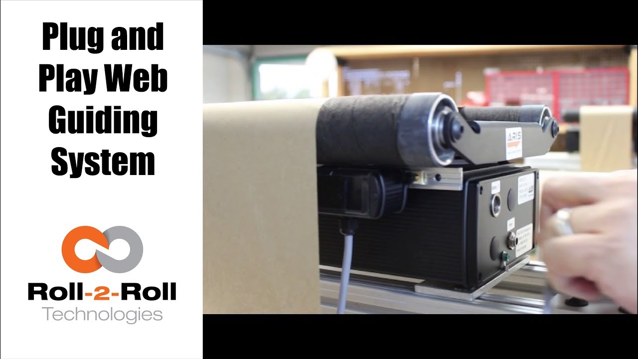
Check out this video to see how easy it is to simply plug in and use our web guiding system without any type of setup or calibration.
Transcript
Show full transcript (324 words)
this is February Lascaux of rolls roll technologies in our series of showing you about that some features of our webcast and today we want to show you how simple it is to install the cat just to put it in operation right now we're showing you a 12 inch web guide which if we have installed in our testbench and it's a really simple it's four points where we actually fix it to the Machine and what happened the same one you're in your facility now in this case we already thread the machine the web guide with some the two and we have position the sensor where we would like to show a habit position as you can see it's a very simple sensor so it only has one face and so it's a taken away from the u-shape remember our sensors can actually detect any kind of material without having to be adjusted and now as you can see on the back side of our guide you can see that there are only two positions that we're going to plug into the first one is we plug in the sensor we have actually identified the sensor position sensor 1 and then we connect our power supply just fix it to it and if we look at the other side that as you can see the web guide reacted because it's already in operation let's go to the other side to the front and you can see our panel right here see and now it's indicating that it has located the sensor and it's ready to go and now I'm going to put this machine to work as you can see this is a very simple installation what we did let's just plug into two cables and when the key is operational come with us to Roloff acknowledges and this melts you understand more or less and how I guess didn't plug in place
February 3, 2018
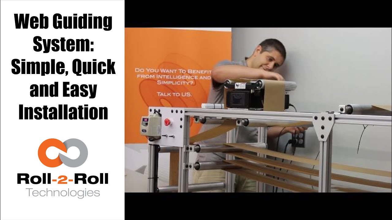
This video shows how easy it is to install the Roll-2-Roll Technologies Compact Web Guiding System. The complete installation and commissioning can be done within seven minutes.
Transcript
Show full transcript (366 words)
In this video we show how quick and easy it is to install an ARIS Web Guiding System. Unpack the box and lay down all the components such as the cables, web guide mechanism, the web position sensor and power supply. The compact web guiding system is pre-wired for easy installation. All that is required is a single allen wrench tool to fasten the web guide to your machine frame using the mounting holes at the bottom of the web guide.
We even provide the 6 millimeter mounting screws with spacers to make it really quick and easy for you. Carefully unscrew the four mounting screws and spacers from the web guide. Place the four spacers over the pre-drilled mounting plate on your machine. Carefully set the web guide over the spacers paying attention to the direction of travel of the web.
Use an allen wrench to securely mount the web guide onto your machine frame. The compact and lightweight design of our web guiding system makes it easier for quick installation on your machine. The mounting holes also provide the necessary electrical grounding of the web guiding system if the machine frame is properly grounded. Please refer to our user manual for more information about grounding.
Next mount the web position sensor on the aluminum rails already mounted on the web guide. Use the thumbscrews to secure the sensor to a desired position. Using the 12 pin DIN connector on the sensor cable, connect the sensor to the web guiding system Make sure to thread the sensor connector all the way through to secure it in place. Next connect the power to the web guiding system using a pre configured power supply.
Once the web guide powers ON set it to automatic control and the web guide is ready for operation. NO other setup or calibration is required. The intelligent control system takes care of the rest of the settings for the sensor and the controller. We have spent the time on R&D so that you save every minute of your valuable time.
That’s how quick and easy it is to install our guide. All in less than 7 minutes. For more information please contact us.

February 3, 2018
Roll-2-Roll Technologies shows just how easy it to set up its web guiding system. The automatic function does all the work, so you don't have to. Just press the automatic button and let it roll.
Transcript
Show full transcript (248 words)
As a real plug-and-play system, ARIS adapts to any material, requires no calibration, and very little set-up time. First plug in the sensor to the 12 prong outlet in the back of the machine, using the guide notch that aligns the plug to the outlet. Once the sensor is plugged in, tighten the lock collar to hold the sensor cord in place. Slide the sensor into the sensor guide rail.
Make sure the middle of the sensor is aligned with the material’s edge. Once connected to a 24 volt power supply, the user operator interface featuring language independent icons will come. A green sensor indicator will verify an operable sensor. Above the icons you will see the material edge, position indicator, represented by a green and red bars.
When the material is in correct position, you will see one red bar and one green bar. If it's incorrectly placed, you will either see no green bar or red bars on both sides of the green. Once the sensor has been aligned with web, secure the sensor using the thumb screws. When the screen turns on, the automatic/manual icon will indicating the guides last operating condition.
A green icon indicates the guide is in automatic operation. A red icon indicates the guide is in manual operation. The operator can change the condition by pressing the icon once. ARIS does most of the work through its automatic option, so press the icon to set to green and let it roll.

February 1, 2018
Are you tired of wasting time trying to calibrate your sensor on your web guiding system? Our sensor technology allows you to get away from the old calibration needy technology and makes installing and commissioning the edge sensor a simple operation. Check out how simple and easy it is to install our sensors for edge guiding, line guiding, contrast guiding and width measurement applications of any kind of web materials.
Transcript
Show full transcript (436 words)
Hi, this is Pedro Velasco with Roll-2-Roll Technologies. We've all seen the videos that show you how to calibrate a sensor for edge guiding purposes. It's a lengthy process, with many steps, complicated to some people to the point that we have we've seen in some converting lines the procedure posted so that the operator can follow the steps required for calibration Well, that is Old Technology. Our technology came into the market three years ago with a revolutionary way of sensing where you don't have to do any calibration.
Here we show you how easy it is to install these sensors in comparison to the old processes where you have to go through a calibration step by step. This is the ARIS SCU5 sensor control unit. It's a very simple lightweight unit that is available with a screen or without a screen depending on your needs, but it can handle up to two sensors at a time. Today we will show you how easy it is just to get our sensor into operation with the sensor with the control unit.
First, plug the sensor control unit to a 24 DC power supply I have installed a ARIS WPS 221 IR sensor which has a 221 millimeter sensing window and an infrared light source. All I'm going to do is just plug it in. Once I match the plug to the notch I can just put it in place and the ARIS SCU control unit immediately recognizes what type of sensor we have in is it a white light or an infrared sensor even the size of the sensor, so you don't have to worry about that either and we're going to set it up to edge mode right. As soon as I place the material in front the sensor it is immediately detected.
I did no calibration for this. I can even change the material and put in something that's difficult as this, which is a bubble wrap and in it detects it. Not only that, I can change it to detect a string, count the number of strings, the position of the string. These are just some of the applications.
What I wanted really to show you was that this is all you have to do in order to get our sensors into operation no calibration at all so why waste your time using old technology where you have to go through a lengthy process of calibration, when you can have this, which allows you to do all that in just a couple steps. To see more video materials on our website www.r2r-tech.com.

February 1, 2018
Do you have an existing web guide with outdated sensors and control unit? We now have a solution with our upgrade kits featuring Roll-2-Roll® Web Sensors and Control Units for all electromechanical web guide systems, providing advanced edge and center guiding capabilities.
Transcript
Show full transcript (2182 words)
Hi, this is Pedro Velasco with roll-to-roll technologies in a previous video we showed you or we talked to you about the advantages of using a retrofit kit when you need to replace your existing web guiding system especially if you're a integrator or a rebuilder of machinery even an end-user. This is one way to save some money, so you keep the mechanical part of your web guide But then you use a retrofit kit in order to improve its application now You're getting the best in controllers and the best in sensors technology available at that time so Whenever you order a kit from us you'll probably get a Control unit which is clearly labeled and helps you in the orientation as to how the screen will be. So you will have the sensor Ports and then you will have on the side power connection the motor connection And if you have order an Ethernet communications option it will be there, too. You will also get a sensor or sensors depending on what your application Maybe even a sensor rail if you need so But that it's up to the user as to where they want to place the sensor.
You also get an actuator With it's a own motor driver and then a servo-center sensor with its brackets right. And then all the other accessories are required in order to do the installation. Ok so the first thing you would like you would want to do when you receive your Your kit is you want to verify that it it's in working condition I mean we do packages the best way possible we want to avoid any problems. So the first thing you do is you power up your control unit and you will receive a Connecting cable like this, but for the sake of this demonstration.
We're just gonna use a pre connected power supply. So you will connected to your power power right and then the screen should light up right and then you can proceed to Connect your sensor now remember our technology allows you to do this without having to do any calibration so it's a very simple and a very simple operation so Here you go, so I have now connected my sensor And I can verify if it's working as you can see on the screen, it's working so that we have done that step so After checking your the control unit with the sensor and just powering it up we want to then proceed to Installing the motor so when you get the motor or the actuator you will get an actuator with the mounting bracket And the motor driver okay? So first of all we just want to do is we're gonna do a wiring here Show you how to how you can connect the wiring, but typically we will give it to you pre-wired now There are some exceptions people have some special requirements And they want to do a wiring themselves, but will also give you instructions how to do the wiring. But in this case we're just gonna go through the whole process so first of all you would have to install the bracket I'm gonna use this The plate that we have for the demonstration purposes, but you would have to have this already pre-drilled It's a 4m 4mm screws and then we just Do the just put the bracket on and screw the bracket on to the plate so one thing that you have to be Cognizant of as we're installing the bracket We also have to install the servo- center bracket.
Now the service center bracket now only has one position it goes to this side right so you have to install it at the same time you're installing the motor bracket and so you use your 4mm 4mm screws and you have to install it within the brackets into the plate So here I show you that I have installed the bracket and installed the other bracket for the motor or for the actuator and the bracket for the servo-center As you can see I have the screws mounted here in here right something you have to consider you have to align the motor make sure that this bracket aligns the motor with the the Connection for the actuator to the web guiding mechanism right and of course the servo- Center. It has a one position only so and that will get installed in the next step. Okay, so once I have all the brackets installed then and I have aligned it then I place the motor and notice that I am placing the motor with the cable side on Opposite of where the several Center bracket is at right. I would screw this on and then I would get the servo Center sensor So in order to install the servo-center when it comes it has two nuts right and so you Put it through the hole on the servo-center bracket install the Locking nut and just Score it back on and one thing that you have to do is we recommend that you have the distance between the face of the servo Center sensor and the screw of the actuator An eighth of an inch is a pretty good distance that will work enough and you can actually adjust that by just adjusting the back Nut in order to create the space Okay, so now that we have installed.
Let me give you a piece of advice because there are certain vibrations on the web guides that is operating and you don't want the servo-center to Sensor to move we recommend that once you have determined the appropriate appropriate distance of the servo-center sensor Just put a little drop of Loctite glue on the back nut and then after you secure the front nut then before you secure it just put a little bit on that too right and that will keep the sensor in position. okay, so now that you have installed the Motor on the motor bracket or the actuator on the motor bracket and the servo- Center on its bracket Then we want to do the wiring. However we provide the driver Motor driver in this enclosure. Now you have two options to put places enclosure within your operation one is a you actually fix it to a plate or something where you can just drill a couple of holes.
We provide the Dimensions for this for you so you can do that that operation. You would probably recommend a m3 and screw on this. However We also provide the option where you can just put it on a din rail, so those are two things you can do when installing. Okay, so When we're going to wire this, it's clearly labeled we will provide you with a sheet where it gives you the locations of each of the wires.
However typically we will send this to you pre wired But in the case that you need to do it on your on your own we have provided this sheet And you'll find that on the p1 section, which is clearly label p1 you will have all the connections for the motor in the Connection from the control unit to the more and on the p5 section. You will have the connections for the servo center unit So before we start connecting cables. Let me give you a word of advice You may not you should not connect the motor Or plug in the connection to the control unit that goes from the motors From the motor driver while the control unit is on This will it's not recommend it so Always every time you can do some operation where you need to disconnect the motor from the motor from the control unit Make sure that the control unit is off Alright, so for the sake of time we went ahead and wire to this. This took us about five minutes to do the wiring but as you can see we followed the table that we have here.
It's all pre-wired according to the table and as I mentioned before never plug the motor driver to the control unit while the control unit is on. So as you can see right now we have we have our control unit off. We're gonna go ahead and proceed and connect the motor driver to it. Now that I've That I've connected the motor driver to the control unit I can proceed to put power to it so Now one thing that we recommend once you do this is just make sure in check that everything is operating so with the control unit on the manual which is when it's lit red.
We can actually check the position of the motor. Just move it around right so We can jog it to one side or jog it to the other side Furthermore we can check the servo-center now. Here's something that we want to tell you about servo- centers sometimes Typically we will send you this already preset But in case it s move or something like that you might notice that the servo- center might be off. It might be because It's in the wrong position, so what you want to do is adjust it.
Now you can find adjust it by moving the servo- center in and out to things you don't want to do you don't want it to be crashing against the the stem of the of the actuator and Second thing is you don't want it to be too far away otherwise it will just go to either one of the Extremes right so once that is set we are ready to then test with the sensor now when we're connecting the sensor to the control unit you have to be very careful because the pins inside the connector are very very fine. So the connector will have a notch and you have to align the notch to the port. So the port rule house will have a notch in there so align those those two and Just don't push it in too hard. Just align them and just screw it right on.
It will come in completely and connect correctly and as you can see right now, so The sensor doesn't detect anything right but right now It's in manual mode, so nothing will happen But I'm gonna check and see and yeah the sensor is actually seeing this the finger in if I put it on automatic Okay it will start moving and then I can verify the sensoring. I servo-ceter again, and it's ready to go when you're specing the motor we actually provide you that the motor comes with an m6 thread On the on the end of the of the shaft motor shaft, however We usually will you know we can work with you if you have another need. Also we can provide you with Different size motors depending on your needs so if you have an application that requires more thrust we can give you a bigger motor or the standard motor that we put in some of our web guides, or if you have a very small application we can use a smaller motor. It's all depends on your needs So all you have to do is just tell us about what your needs are with the motor and you know the connection to this to your web guide it can be you know a Ball joint that you know there's many applications that you can do with this However anytime you need something like this.
We just spec with you we talk to you and we we help you inspecting the The connection for your web guide. So with all the options that we have in motors All the options we have in controls and on it you can apply this to any type of guide Any type of guiding application that you need for example you can use it on a steering guide or a displacement guide even for unwind and rewinds and Just by changing the motor we can use it in any of those applications We we hope this information is useful to you in how to use or how to install one of our retrofit Kits now one thing that we want to emphasize is this is the same technology that is on all our web guides so if you want to see other features that we provide within our control units with our sensors you can look at our some of our other videos that we have through our website. You can see other applications we can do with our sensors. You can see you know how we can actually give you some other features and Make your operation easier to run so We hope this will be a help to you and just contact us or look at our website www.r2r-tech.com

February 1, 2018
Having the right rollers on your web guide is an important part of making it run efficiently. Our web guides makes it easier than ever to use the rollers you need. Watch this video to learn more about removing and replace rollers on our web guiding system.
Transcript
Show full transcript (755 words)
Hi, this is Pedro Velasco with Roll-2-Roll technologies. Today I want to teach talk to you about how to install a roller on our web guides. Now in some situations you might have that you purchase a web guide from us but you require a special coating on your roller. Well we don't carry those in stock but we can tell you where you can find those rollers from one of our suppliers.
And so the best thing we can do is teach you how you change the roller or how you install the roller on your web guide. So when we give you a web guide when we send it to you you will have the shafts for the roller already installed so they're gonna be located here and they're attached with two m8 screws on each side. So just remove the m8 screws and remove this shaft. So this is one of our typical and groove rollers that we have in this case the roller will have when you receive it it will be covered in a black protective fabric and then it will have two rubber bands on the edge so you just take the rubber bands off and leave a protector protective fabric on it until you're finished assembling it.
But for so you will have on, either side, one side of the roller you will have a little bearing which is actually going to help it's a pressure bearing so it keeps a pressure on the shaft as you're assembling it. And then on the other side you will have two set screws that will actually lock the position of the shaft on the bearing. Now these collars kind of move around so they are pivoting collars. Okay so the first step to do is install the shaft into the the roller into the roller itself.
So you go through the collar that has the little bearing ball bearing on it and just carefully install it in there and just push it through right. Now it should go all the way through to the other side to the other collar and then you will have to look on it on this side just to align it. So once you have it aligned just push it through all the way up there okay so it goes out. Now one of the things you'll notice is we have to kind of center this shaft on the roller.
One of the best ways we found out is this measuring the distance between the end of the shaft to the on the on the roller. You could use the vernier for that. So we'll just take some measurements here. This one has a hundred point one six zero inches on one side and on the other side it should be very close to that.
It has point one eight one. I'm gonna measure that again point one eighty five. So what I do, this is pretty close to center, so what I do I just give it a little tap on one side and see how much it moved. Point one six six point one seven seven- that's close enough.
Okay so I have a ten thousandth of an inch difference between either side so that. So now we proceed to lock the shaft in place now the roller face will have a little cutout in it which is gives us access to these set screws. So you align the set screw to the to the cutout and just tighten it. Now for this you will need a 1/8 inch allen wrench.
so once you have it set and tightened then you can proceed to install the roller onto the roller plate. And this is a fairly simple operation just align the holes of the shaft to the holes on the rollerplate. Place your m8 screws on it just throw them on and just finish it off by tightening with a 5 millimeter allen wrench. And just give it a once you come to the lock just give it a quarter turn that'll be enough.
And you have assembled or placed a new roller on your web guide then you can remove this fabric and you're ready to go. So we hope that this helps you in doing a change of our roller assembly onto the roller plate and just watch on our YouTube channel for more instructional videos. You can also go to www.r2r-tech.com and see other information from our products.