
How to Find the IP Address of Your SCU6x Controller
In this tutorial, we'll guide you through the steps to find the IP address, subnet, and gateway of your SCU 6X controller using the tool icon, power user, and communication settings. Discover the type of module you have - in this case, an ethernet IP module - and ensure you're connected to the correct network to connect to the app.
00:00 Introduction to Finding the IP Address
00:14 Understanding the IP Address Details
00:23 Module Type and Network Connection
Transcript
Show full transcript (80 words)
So, in order to find the IP address of the SC6X controller, we're going to go into the tools icon, bottom right, power user, and then communication. It's going to tell us what the IP address of the devices, the subnet, and the gateway. It's also showing us the type of module that we have. This is an Ethernet IP module. So we need to know that IP address and be inside that network to connect to the app.
A programmable logic controller (PLC) or programmable controller is an industrial digital computer which has been ruggedized and adapted for the control of manufacturing processes, such as assembly lines, or robotic devices, or any activity that requires high reliability control and ease of programming and process fault diagnosis.
Transcript
Show full transcript (1078 words)
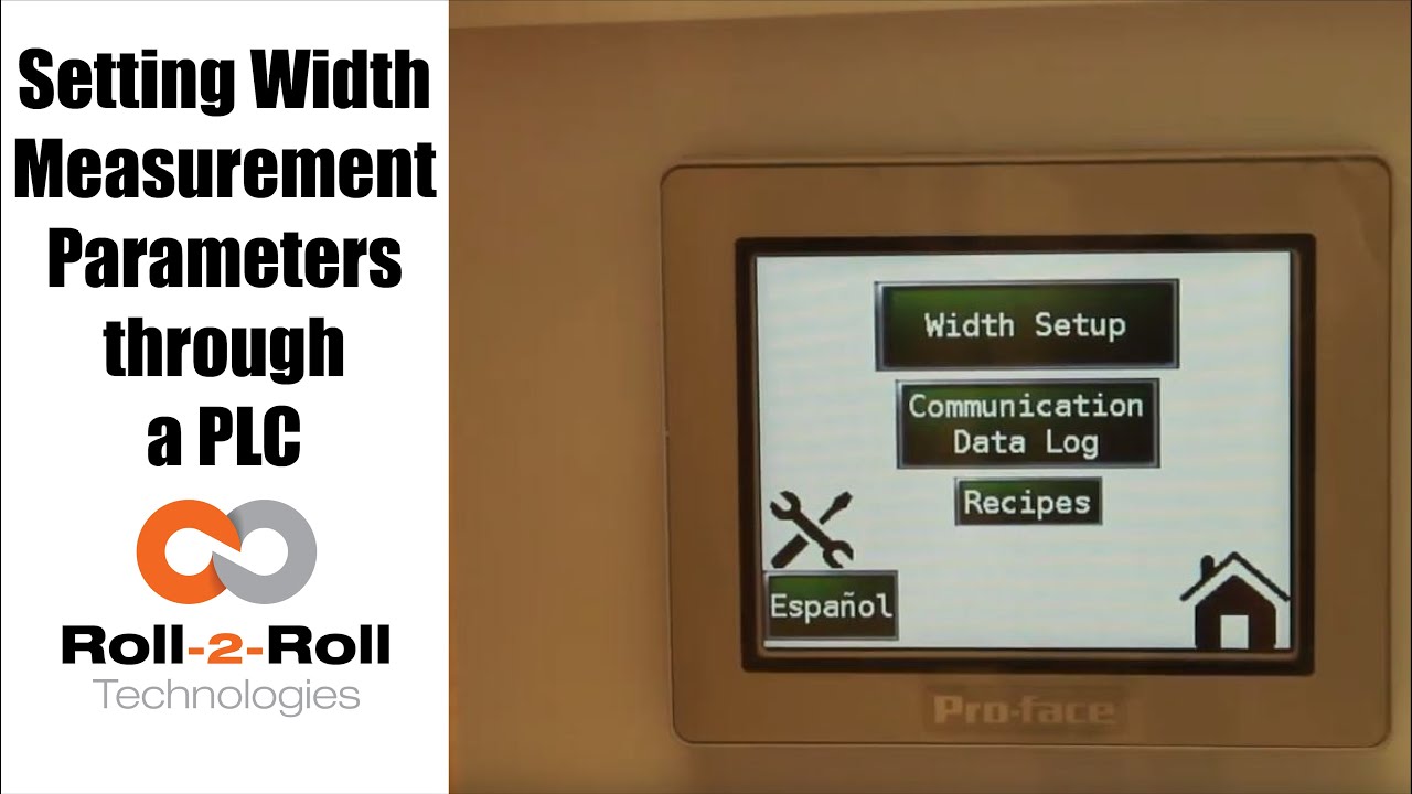
so in order to set up the Center for British Mint and we'll go over this menu once one more time we're going to go to the setup screen right here and then click on width setup then we can enter our nominal width the alarms the warning ranges and all those things first we want to whenever we have a new product in there we want to measure the product what the width of the product is in this case it's 153 millimeters we're going to enter 1 5 3 enter and then we're gonna set the warning to be point four millimeters so if the alarm is less than the warning the system will not accept it so the best way to do that is to make sure to set the alarm first so we'll set the alarm at 1 millimeter and there is a way for us to set a symmetric alarms so the positive range can be 1 millimeter and the negative range can be 0.5 millimeters if we want it to so in this case I'll set it at at 0.8 millimeters and then the warning range in this case let's set it to 0.4 millimeters and we have set everything what we want to do is to say hey this is the right one so we say record wait what it does is it teaches the sensor to say hey this is the nominal width we're looking for and I have presented the web with the right width and it'll take the measurement from then on so if you go back to the home screen it's going to show you the measurement and as long as it's within the range you're gonna have the green light whenever it goes to the warning limit it's gonna go to Amber and then whenever it's about the alarm it's gonna go to the red light these are actually also triggering a digital output on the PLC so we can connect a stack light with three outputs so connect the red sorry red amber and green to the three signals in the stack light the other thing that we want to point out a little bit more is the recipes so sometimes you might not see it you just have to click on this to say display recipe so what we have provided is an option for you to save seven different product recipes you can scroll through them and let's say we want to pick up product seven and we want to use that as the recipe what you need to first do is pick that number click on load and it's going to load the data here right now it doesn't have anything so let me go to one which has something ok so now I loaded product 1 and it had some values there so we'll have to load it once you load it it's loading is just for display purposes you need to press accept to accept that recipe so that it will be sent to the front screen for width measurement in this case I want to make sure to make some changes if you want to make the changes you can directly click on that width value and I'm going to enter 153 and then alarm as one date and then warning as 0.5 once I enter that if I press accept it's gonna send it to the front screen if you ever change a recipe you need to make sure to save it so right now I can press save now it saves it to the memory so that means that anytime you go back to that recipe and come back to one it will retrieve that data so make sure to remember to save it so two things one is if you want to load something it loads it here so we want to do that loads it here and if you want to take this recipe and put it into the front screen you need to press accept and any time you change the recipe you need to make sure to save it so that's the thing about recipes you have an option to say about seven recipes here there is also an option to log the data as you make the measurement there is a USB on this PLC so what you can do is you can connect a USB there and click on start logging it will it will start logging the data and whenever you're done you're gonna say stop logging and it'll stop logging the data and then you can take the USB off from there there are a few other settings here that you can set up as well these are advanced settings there is an option to override the minimum contrast in our sensor the minimum contrast is used to say whether something is an edge or not in the picture so by default we have 50 so we can have that and if you want to enforce that you need to press this button so that it changes into lime green instead of dark green whenever you want to disable you press that it disables that and this is the place where you can enter the value you can also make the sensor provide the data that is already filtered so if you want to do that you turn on the filter turn the lime green turn off the filter it goes off this is an advanced feature which is called as a minimum measurement quality whenever we take a measurement we have an output called quality factor and we can set that nominally it's ten millimeter ten is the minimum quality factor now if you want to make it higher you can set that value and enter it there so as long as there is a value it's going to take this value if you want to disable that option press n zero so I press ten and enter and it'll be that that's the minimum that you can provide so this screen is more like an advanced screen your operator wouldn't really have to do this only people engineers that are setting up the system can use this for troubleshooting purposes and stuff like that and yeah that's about it so these are the features there and like we talked about before we also have the option to log the data and showing the log of the data right here you
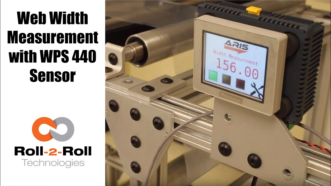
Roll-2-Roll Technologies offers robust width measurement capabilities with the WPS 440 Sensor. Using a PLC connected via ethernet, we are able to accurately measure the width of any material.
Transcript
Show full transcript (1727 words)
well today we just want to show a little bit more about our width measurement application with our 440 sensor so we have the 440 sensor installed and then you have the web coming over it we have installed two support rollers so that when the web moves it doesn't flutter too much we want to avoid fluttering whenever we do web width measurement this sensor is actually connected to Ethernet IP so you can connect it to a a PLC like this or we also have a web browser interface on the computer that you can connect to so the main things are here is how far the sensor is from the web right now we have installed it at about 5 millimeters from there that's the optimal distance that we recommend the sensor is installed facing up that is good but just to avoid any dust and other accumulation it may be better off to face the sensor down so that it's looking down towards the web a few other things that we need to consider is the the the free space behind the sensor we want to maintain about six inches of free space so that nothing in the background is seen by the sensor that's the optimal way in which we can get the best results there's also a way for us to get the maximum scattering out of the sensor if you want to do that what we would do is we will raise up this roller so that the web comes at an angle now about 10 15 to 20 degrees is the angle that we want and it depends upon the orientation of the sensor so if we if you want to get the maximum scrap scattering what we will do is we will raise up this roller so that the web comes this way but those are the few things that you want to consider before installing our 444 width measurement application other things to consider is this free span doesn't have any twisting so we don't want to install the sensor right next to a dancer roller or right next to a web guide we want to install the sensor between two fixed rollers so that we have a fixed pan and then web doesn't flutter that will be the ideal scenario what we were going to show right now is how do we get this up and running right now as you can see we have the power on to the sensor it's connected to Ethernet IP right now it's connected to a network device like a router or a switch so you can connect to the sensor through the network if you don't want to do that you can directly connect the sensor to the computer or you can directly connect this to your PLC or our PLC for that matter so just for demonstration purposes we're going to connect it to both the computer and the PLC to a network the next thing that we want to do is to connect the sensor to the PLC one of the first things that we want to do is find the IP address once the sensor is connected and powered up and connected to your network device we can pull up a utility called IP config we have information about that on our website we can go once you open up open up open up that program it will show what device there is and what's the IP address of that right now the device is said to have DHCP set automatically and it has an IP address 0 dot 0 dot 0 this is happening mainly because the Gateway doesn't match so what we would do is to make sure that they get the Gateway matches let's do that the Gateway is one one sixty eight dot one dot one and AP address of this device so right click configure on my parents one point something see you so once we do that we set a static IP address with the Gateway and everything now we can right-click and pull up a web browser and that's going to bring up our dashboard so this dashboard basically shows us several things the web measurement is shown here so this is the web in that the width measurement is 155 and something millimeters we also have a filtered width measurement we have a filtering algorithm that would take the filtered value of the raw measurement and then edge location which is left edge so that's saying where this edge is and then the right edge is showing where the other edge is and then within our software we also have what we call it as a quality factor which is basically think of it as how good of an image or how good of an edge that is so it says that the left edge has a quality factor of 300 and something and the right hand has a quality factor of 100 and something so this is a easy and quick and easy way to test our sensor make sure everything works fine we have a plot that shows the weight the measurement we also have other things that we can do with the sensor in terms of adjusting the brightness all of these are shown here so the idea the main thing that we want to do is make sure that the quality factor on the both edges are pretty high and as we mentioned before one of the things that improves the scattering is angling the sensor either we can lift this roller up or angle the sensor so that we get a pretty good quality factor so if you can notice when I move that since we don't get a good scattering the quality factor went down but if we install the sensor at the right about 15 degrees angle then we get a pretty good quality factor signal and then you get the measurement there so this particular web browser interface allows you to pan the data plot the data you can also save the data if you click on the save it stores that data as an excel file with all the information that we collect which is shown here such as the brightness and and the edge position and the width and everything so that's basically about the the web browser interface as you can see we can run the web and it collects the data as the web is moving over the sensor let's move on to the PLC and kind of show you how we can set up that PLC this is a special software that we install on it basically for customers who doesn't want to set up their own system they have the ability to use our PLC that we supply to do width measurement and also have the ability to provide a trigger measurement whenever the width varies so one of the first things that we want to do to get the PLC communicate with the sensor is to tell the PLC what the IP address of the sensor is in order to do that we're going to press these corners one after the other and then go to offline and this shows up the main screen here in the offline menu we click on peripheral and within the peripheral we're gonna select Device slash PLC setting and here we're going to use the ethernet/ip explicit messaging protocol so that's the one that we're going to select and then these settings are fine which is the standard setting the main thing that we want to set is the IP address of the device so we're going to go click on device and then set the IP address so right now it's set to 192 168 1 8 so our sensor IP address that we manually set was 192 168 1 dot 100 so we're gonna type in 100 enter and exit and then Save Changes so now the PLC is going to reboot with the new IP address we just have one more step to do to connect the PLC to the sensor or connect the PLC to communicate with the sensor and that's to enable the Ethernet communication so in order to do that we're gonna go into the settings and communication and turn on internet might be once we do that now we got the measurement from the sensor so this is the real-time width from the sensor that is going here now if the customer wants to set a few things for example if they want to teach the sensor so that we want to avoid any inaccuracy in accuracies in the measurement what we will do is we will put the web where at the location where they desire it and measure the width of the web then let's say in this case it's 155 millimetres would go in and press this 155 and press record width now they can also set warning and alarm ranges so for example we want to say alarm is for 4 millimeters warning is for 1 millimetre and going so as long as the width is within that range which is 155 we taught the sensor for that width it'll show green and whenever the width goes about a millimeter high or low the amber would show up and then when it goes about the warning the red would show up so and that's pretty much it right now we're seeing the weight variation because of the curls and all these things in the web we're trying to show or simulate some of the things that you would see when the weight varies by these curling there's also an ability for the customer to set recipes so if they have different product with you can set what is the nominal weight what is the alarm weight what is the warning with things like that you can load them you can save them and so on and so forth and also there's an ability to connect a USB here directly and save the data through the USB on this PLC right here and this PLC can be connected to an signal alarm signal lighting system with green amber and red so that it's readily visible for the operator running the machine so that's pretty much our width measurement system using our WPS 440 sensor you

ARIS Web Position Sensor can automatically detect any material without the need for calibration. This video shows the sensor capabilities, such as accuracy, precision, linearity, with four materials.
Transcript
Show full transcript (327 words)
Our web guiding system, ARIS, features the latest in web guiding technology. It adapts to any material, requires no calibration, and is very simple to set-up. Our technology allows the sensor to be material agnostic, which means ARIS accurately detects the web edge position of any materials used without the need for manual adjustments. ARIS’ sensor technology works differently than any other currently available sensor in the market.
It uses the reflection of infrared light to take a picture of the edge of the material. This picture is then processed using digital signal processing algorithms to accurately sense the true position of the material irrespective of its physical properties. Other sensors use a blocking technique where the web is used to block light, sound or air. Since the amount of blocking depends on the material properties, the current sensor technology is less accurate with porous or transparent material.
Ultimately the web guiding performance is affected by the inaccurate sensor measurement. In this experiment, we will show you four materials, black nonwoven material, white nonwoven material, transparent film, and burlap. Our experimental setup is equipped with a high precision motor stage which moves the web material, which is 10 mm away from the sensor, back and forth. This setup is used to quantify the sensor performance.
With each material we repeat the exercise four times. The green line represents linear regression, which quantifies the precision and accuracy of the sensor. The blue represents the actual position of the web as measured by the sensor. Follow the results as the experiment progresses.
The video shows the web as it moves away from the center and the sensor’s ability to follow the position. The experiential results clearly show that the precision and accuracy of the sensor is unaffected by the material properties. Our sensor has linearity of plus or minus 1 percent without any calibration. Find out more information about ARIS and our sensors, using the link in our description below.