
Available Downloads

LHS-030-xxxx-RF -- High thrust retrofit actuator without linear support
STP 154.4 KB
Download
LHS-030-xxxx-RF -- High thrust retrofit actuator without linear support

Available Downloads

LHS-020-0400-TG -- Retrofit Actuator with Side Support
STP 7.4 MB
Download
LHS-020-0400-TG -- Retrofit Actuator with Side Support
SKU: 6-144005
LHS-020-0400-TG
  • Linear Hybrid Stepper Actuator
  • Correction Rate: up to 0.59 in/sec or 15 mm/sec
  • Maximum Thrust: 200 lbf or 890 N
  • Maximum Stroke: 4 in or 101.6 mm
  • Mounting: Front and Rear Rod Eye Bearing
  • Mounting Type: Floating

Available Downloads

LHS-020-0400-RF -- Retrofit Actuator for Supported Rails
STP 119.5 KB
Download
LHS-020-0400-RF -- Retrofit Actuator for Supported Rails
SKU: 6-144004
LHS-020-0400-RF
  • Linear Hybrid Stepper Actuator 
  • Correction Rate: up to 0.59 in/sec or 15 mm/sec 
  • Maximum Thrust: 200 lbf or 890 N 
  • Maximum Stroke: 4 in or 101.6 mm 
  • Front thread: M6x1.0
  • Actuator Mounting: NEMA 23
  • Mounting Type: Fixed Mounting

Available Downloads

LHS-020-0600-RF -- Retrofit Actuator for Supported Rails
STP 120.3 KB
Download
LHS-020-0600-RF -- Retrofit Actuator for Supported Rails
SKU: 6-145004
LHS-020-0600-RF
  • Linear Hybrid Stepper Actuator 
  • Correction Rate: up to 0.59 in/sec or 15 mm/sec 
  • Maximum Thrust: 200 lbf or 890 N 
  • Maximum Stroke: 6 in or 152.4 mm 
  • Front thread: M6x1.0
  • Actuator Mounting: NEMA 23
  • Mounting Type: Fixed Mounting

Available Downloads

LHS-005-0400-LP: Small web guide actuator
STP 89.5 KB
Download
LHS-005-0400-LP.stp

<span>How to Set the Actuator Parameters in SCU5 Controller</span>
November 30, 2023

This video shows how to set the actuator parameters on the SCU5 controller. 

Since Roll-2-Roll Technologies offers several different actuators from different vendors, this allows for lot of flexibility for the end customer. 

👉🏻 More information on the actuator are here: 🔗https://r2r.tech/products/roll-2-roll-actuators For more information about the SCU5 controller please visit: https://r2r.tech/products/roll-2-roll-controller.

Transcript

Show full transcript (1887 words)

hello everyone this is arvind seshadri from Roll to roll Technologies today we're going to touch briefly about our actuator settings how do we set different parameters on the actuator on our scu5 all of our su5 controllers have the ability to connect to a variety of different actuators that are driven by stepper Motors we provide our own drivers for it if you look at our documentation you can see that from the su-5 controller we go to a motor driver through the motor communication cable and from the motor driver we go to the actuator through the actuator cable because we have the flexibility to connect a multiple different types of actuators we also provide the ability to set up some of the parameters of the actuator through our su5 controller that's what we're going to look at today and we're going to see how to set the stroke of the actuator the pitch of the actuator the speed the polarity and so on and so forth we do have our one of our actuator connected right now to the scu5 controller and that's the one right here and this is this is our standard upgrade kit actuator and this one has a front spherical eye and a rear spherical eye and then it has bearing supporting the the actuator to extend and retract and this is our LHS series with a four inch stroke this actuator also has a Servo Center sensor that is installed right here and that's actually looking at the rail that is going in and out the servo Center basically allows us to quickly Center the actuator or home the actuator to a position which makes the web guide be parallel to the other rollers within the machine we'll also go through that in another video but essentially we have our actuator connected here and then if you use our sc5 controller to move the actuator you can see that the actuator is moving back and forth and that's also seen on this bar graph right there so we'll take a look at how we're going to set some of the parameters that can be done by going into the tools icon and then power user and then actuator and this provides you with some of the settings that are currently available and this shows a pitch of 0.25 inch a stroke of 1.38 inch there's also a motor polarity setting here and then the speed and the acceleration but when we ship our controller we based on the actuator that is purchased we preset those values in the controller and ship it but if you want to change it it's pretty simple so for example if I want to change the speed I can just drag this right there and set the speed and we can also change the acceleration the speed and the acceleration can be changed independently and the pitch of the actuator is depending upon what the actuator is and that is basically one revolution of the motor how much is the actuator going to extend or attract in our case this particular actuator has a pitch of 0.25 inches and that's what it is set up there if you need to change the pitch you can just press this button and it's going to increment or decrement the pitch the units right now is shown is in inches and if you want to see those units in millimeters you can go to this screen hit the operator icon hit the display and change the units to millimeters and once you do that you can go back to the power user actuator and you can see that the actuator units are now in millimeters this is about 6.5 or 0.25 inch approximately and then the stroke is 35 millimeters and you can probably set it to the stroke on the actuator the stroke that you set is not the actual mechanical stroke that is available on the actuator this is just an electronic limit in order to avoid some of the pitfalls with existing some of the other actuators that are available where if there's issue let's say the web breaks the actuator may go back go to one side and it might keep driving because it has Reach This limit it doesn't know it has reached this limit and it keeps driving it and that might burn out the actuator to prevent that from happening in our case we actually have an electronic limit that means that if the actuator reaches its electronic limit whether the actuator whether there is a mechanical limit or not it will stop just to show you how that works I'm going to set the stroke to be some really small number let's say 30 millimeters and if I go back to the home screen and I try to jog the actuator you can see that it's going in and right now the actuator position is it's showing that it has reached it's fully retracted limit even though if you look at this actuator there's a lot of stroke remaining so if you look at here there's still a lot of room for the actuator to retract more but it stopped at this electronic limit just to prevent it from burning or destroying the motor so the electronic limit can be any limit that you set and that limit of whatever that the stroke that I showed again if I go back to the screen and to the actuator you can see that the 30 what that 30 means is that it's going to be 15 from the middle of the actuator position and on one side and then 15 on the other side and that's what the stroke means so if you are in the middle position of the actuator you can go 15 on one side and 15 on the other side that's what the stroke means in terms of setting there's also the polarity so what we can do is we can change the polarity and if you remember when I did this when I pressed the Plus it was going in a certain direction and if I do this when I press the plus it's actually extending in the previous case when I pressed the plus it was actually retracting and that's also shown here in this position when the polarity is the standard polarity the plus will increase the actuator position and that's what this is showing and the negative will decrease the actuator position so it's retracting if we reverse the polarity then it will do the opposite and again when we reverse the polarity that it clearly shows here now if we press the plus it's extending retracting and then if you do the minus it's actually extending so the polarity can be changed as I'm moving the jogging the actuator back and forth one of the things that you can notice is that the this bar graph changes color and right now it's in yellow or Amber and then if I go to another limit and now it becomes red this is more evident in the other direction so if I go all the way in the other direction this is going to be yellow and then if I go reach a certain it goes to Red this is a quick visual indication for the operator to know that the actuator is close to its extreme position if not at the extreme position if it's in red it's within 10 percent of the extreme position limit and if it is in yellow then it's between 20 percent to 30 percent of the extreme limit so we don't typically like to run the web guide in this position is that there's not enough room for correction in this direction so if there is an error in this direction and the actuator needs to move that way there's not enough room to correct for it so anyway a quick visual indication for us to see where the actuator is again if you want to see that in a bigger screen if you just click on that motor icon then you can see that the same bar graph that you saw on the home screen that's essentially the things with regard to the stroke and the pitch and the the speed and the polarity again just to reiterate there is a difference between the mechanical limits and the electronic limits the mechanical limits are the actuator cannot move anymore because it's mechanically inhibited and we never want to set that actuator or install the actuator in that scenario where the mechanical limits are reached the electronic limits are just safely limits and this allows us to stop the actuator from moving even before it reaches the mechanical limits so we typically suggest that you install the actuator move it back and forth find the Home position set the home position or this Servo Center position and then set a certain stroke and then jog all the way to one side make sure that it doesn't hit the electronical limits and jog all the way to the other side and make sure that it doesn't hit the mechanical limits and as long as it doesn't then the electronic limits are fine if in any scenario whether you're going jogging left or jogging right it hits the mechanical limits then you would have to reduce the electronic limits so we never get into that situation where the actuator might hit the mechanic that's all we need to do in terms of setting up the actuator in terms of the stroke and the pitch there are other few functionalities that are available for certain controllers for example the actuator position if it reaches the extreme position there is a way for us to set digital outputs so that not just an operator needs to look at it but the digital output can provide a signal to the PLC to alert PLC that hey the actuator has reached this limit the other option that we have this is mainly for our big actuators that are moving the unwinds and rewinds which are susceptible to damage if we reach the mechanical limit that we can add additional limit switches either mechanical limit switches or even electronic limit switches make sure that the mechanical limits are never reached and if we have that option if we have the hardware provided with your actuator then you have the ability to enable them the way to do that is to get into the tools and then the power user and then in the controller there's this limit switches icon button and then we just need to turn on the limit switches if you don't have the limit switches and you turn on the limit switches the actuator might not move just be aware of that but if you do have the limit switches and you want to enable that functionality then you can enable that functionality by turning on the limit switch so those are the basics of the actuator settings in terms of stroke pitch polarity limits and limit switches in a subsequent video we'll talk about the servo Center functionalities but in the meantime do subscribe to our Channel and we'll see you in the next video


<span>Setting the Parameters of SCU5 for Servo Center Operation using a Physical or Electronic Position.</span>
May 16, 2023

How to set the servo center position or the home position using the SCU5 controller.

  • 1: 22 Physically installating a proximity sensor to detect the home position.
  • 4:32 Changing the polarity of the servo center sensor.
  • 5:39 Some common problems with servo center or proximity sensor installation.
  • 7:00 Servo center position based on the electronic actuator position.
  • 8:30 Setting the servo center position electronically.

Transcript

Show full transcript (2140 words)

hello everyone today in this video we're going to discuss how we can use our upgrade kit actuator and specifically how do we set the servo Center position Servo Center is basically a term that an industry term that is intended to mean the center of the servo or the hydraulic cylinder but over times it it has changed but essentially what it means is that if you have a web guide mechanism and you want to thread up the web on the mechanism and is there a quick way for us to set the actuator to a position that would make sure that the web guide is parallel to all the other rollers in the machine and historically it's been called the servo Center position you can also call that a home position or whatever you want to call it but the ideal thing is that if the web guide let's say you stop the machine the web guide is to one position and you want to quickly bring that web guide to a home position or a center position and that's what is called as a Servo centering in our system or in our upgrade kits we do provide a couple of ways in which we can achieve that functionality one of the things one of the ways in which we achieve that is by actually physically installing a sensor we call it a Servo Center sensor to detect the home position in this actuator that we have um you can see that there is a sensor that is installed this is basically an inducto proximity sensor it's trying to look for this Race Rod when this Race Rod moves back and forth you can see that the servo Center there's a light on that switch there's a light right here and that light will actually go off or on in this upgrade kit actuator the servo Center functionality is enabled by using the serval Center sensor all that the sensor is doing is trying to locate this Race Rod and the transition from seeing the racer rod and not seeing the Race Rod is basically the home position so just to illustrate that I'm going to move this actuator and you can see that there is a LED kind of thing that lights up and if I move it out and that turns off and that is essentially the servo Center position when you install this upgrade kit on your web guide mechanism what you can do is you can actually Center the web guide manually by jogging left hand so you can jog it left and right wherever you want it to and then the position where the frame is parallel to the rest of the rollers in your machine once you've figured that out then you can actually move this mechanically move it to the location where you think that Servo Center where that transition is going to happen and that that would be the easiest way to set the server sensor okay so just to show that the servo Center functionality we're going to show what happens when we hit the servo center button on the scu5 controller so if I go back to my controller and let's say I have jogged the web guide now you can also see the actuator position on the top right and if I hit the servo center button it's going to go until it sees that proximity switch and the light turns on so if I'm coming from the direction where it doesn't the light is off it's going to go until the light turns back on and if I do the opposite let's say I go in this position where the light is on and then I hit the servo center button it's going to go until the light turns off and then it's going to start turns off and then it's going to stop there so that's how you install the servo Center on our actuator in terms of how what the location is based on the centering there are some situations where you might not have the ability to install the sensor we do have a we do provide an additional option where we can change the polarity of the servo Center so this can be done for one of two reasons the proximity sensor that we have right now it's an npn PN normally open and then let's say you bought an npn normally closed then you can just change the polarity on the servo Center and it'll still work and the other thing is that instead of looking at the the actuator position from the back if you want to look at the actuator position from the front then you can also switch the polarity the way to switch the polarity of the servo Center is going to be tools and then the power user on the bottom and then to the actuator and then there's the servo Center polarity now if I change the polarity it's going to work the opposite way so you can change the polarity I'm not going to show that but anytime you install the will Center sensor on the front let's say then the polarity of the actuator the polarity of the servo Center needs to be changed and that's essentially how you would change the polarity one of the common things that happens or common issues is that it's possible okay one of the things that happens is that our proximity sensor is not installed properly and that when the Target or the Race Rod moves back and forth the proximity sensor doesn't light up so I've just simulated that condition right now and just if we take a closer look at the actuator and when I move the actuator back and forth the light never turns on and it's possible that the operators are not aware of this situation and in that case if they actually press the the servo center button where the proximity sensor is not installed properly this is what would happen so if I press that button it's going to try to go to a certain limit and then it would come back and stop hopefully it never hit the mechanical but what it did is that it tried to look for the transition the transition never occurred so it manually turned off the servo Center functionality with the proximity switch and then it went to what it thought was the home position so in this case the only way that we figure out that this has happened is if you go into the controller and power user and then the controller icon if you notice that the servo Center functionality has actually been turned off what it means is that we are turning off the proximity switch based Servo Center functionality we're not using the proximity switch anymore to figure out where the servo Center is where purely basing the center position based on the electronic of the actuator just to show you what that means if I go back to the home screen you can see that the actuator position is exactly in the middle right there now if I jog the actuator back and forth and if I hit the servo Center it will still come back to this position but this is not the position with the proximity sensor obviously the proximity sensor is not lit up so we know that it's not based on that it's based on the digital position of the actuator again the proximity sensor is there for definitely knowing where the center position is and especially with stepper Motors there are situations in which let's say the actuator is not sized properly then the motor position that we are keeping track of may not be the actual position of the actuator that's why it's always recommended to have the center not just an electronic Servo Center but in the situation where you have the electronic Servo Center I'll go in and say how do you set the center of that position this is the center position right now and the actuator you can see it's at a certain position what I'm going to do is I'm just going to manually jog it to a position let's say I've reached this extreme position and just to illustrate that this is actually working what I will do is I'm going to reset this position as the new Servo Center position and this can be done by going into the motor icon and then if we press the reset Servo Center and press accept now we are electronically teaching the controller that this position is the new center position just to check let's jog it back and then hit the servo Center icon now it comes back to this electronic Servo Center position again the distinction between the electronic and the mechanical is electronic is based on the motor position that we think what the motor position is and then the the call Servo Center functionality is based on a hard switch like a proximity switch that is installed on the actuator or the web guide mechanism we would always recommend using the physical switch but in case something happens then you still have this electronic server Center functionality again if you want to change it the easiest way to change it would be you change the server center with the electronic limit is to go to this screen and then you can manually jog it to whatever location you want let's say this is the location that makes the web guide frame parallel to the rest of the machine hit the server center button accept and now this is the new position and then when I jog and then hit the servo Center it'll come back to that position that's essentially how we can set the servo Center position without a proximity sensor a physical proximity sensor this concludes our video about the servo Center functionality how you can set the server Center physically using a proximity switch how you can set the servo Center electronically without a proximity switch and also talked about the safety feature in case that the center functionality is enabled but the proximity sensor doesn't get triggered then we automatically go into this safety where we turn off the server Center functionality we also saw that and that's essentially it there's also one fine tuning that we could do let's say I move back this Servo Center so that now it's lighting up yeah now it's like lit up and in the situation where you have already installed the sensor but you installed it at the wrong location so it's in this position you had installed it in the wrong location and you want to correct for that there's a way for there's a way where in which we can do that so the way to do that is to go back back into our controller screen hit the tools icon hit the power user controller make sure that the server Center functionality is now it's on now I'm going to actually do the servo center operation and it stops there this position is not the right position mechanically so we want to manually jog the actuator to the new position so we're going to go into this screen I'm going to manually jog the actuator to this position and then just like what we did for the electronic we're going to hit this row Center the middle arrow and accept and then just to illustrate that it's actually doing what we want it to do I'm going to put that right there just as a reference yep and now I'm going to jog and then hit the servo Center all of this happened really quick but what happened was it kept moving until it hit the proximity switch once it hit the proximity switch it moved to the offset position so just to show that again and just to illustrate it maybe I can change this lower the speed okay I'm going to move that hit that it's going to hit the mechanical limit and then it went to the offset now if I go this way it's more illustrative so it's going to go to the proximity switch limit and then it went to the offset it took two steps to go there so that's a way in which we can add an electronic offset even with a physical proximity so this concludes our video about setting up the server center operation please follow us and subscribe to our Channel and look for more videos about how to use our system for your application thank you


<span>Web Guide Actuators</span>
September 15, 2019

Roll-2-Roll Technologies doesn't just cater to the narrow web guide applications. Our line of actuators can help you in both narrow and wide web applications at any point in your converting process that requires accurate and precise positioning of your web.

Electromechanical actuators are used when quick reactions to changes in the web position are needed. The actuator connects directly to the control unit.

Transcript

Show full transcript (657 words)

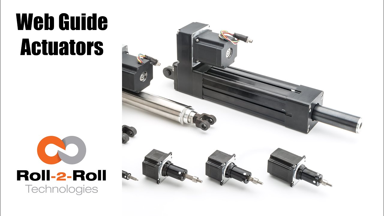
hi this is petrol in law school with roll-to-roll technologies most people think of us as a narrow web company but we actually go into the white web applications - and to show you that we want to present to you our wide range of actuators available for both narrow web applications and white web applications in this front row I have for our narrow web applications these are the actuators that we use in our smaller web guys they go up to about for up to 22 inches in width and so they can handle web's up to 20 inches in this case this a small actuator is what we use it can handle up to 50 pounds of thrust so 450 pound tension applications and it's what we use in our low profile web guides then we have our our larger actuators which we use for applications such as our compact web guide and these can also go up to 50 up to about 150 pounds of tension and then we have the double stack actuator which we use in bigger applications and these can go up to 200 pounds force so they're all available for you for narrow web applications also we have an application for our retrofit kits in this case I have one of our featured actuators which you can see it also has mounted the several Center on it now this is a very robust application it can be provided with you with eyebolt terminals on either side or we can easily with clevis doing so if you have a web guide in your in your plant that requires you know the mechanical parts are all good the controls are update outdated you can actually we can provide you with an actuator and our controls and sensors to it so this is more or less the setup that we will probably we can mount it either through the eye bolts we can mount it through clevis or we can mount it directly on a any fitting that you might have on your machine these are very easy to install and they come already with the several Center mounted on them so it's all up to the particular application that you have in a problem that you want to solve another area that we want to talk to you about is on our terminal web guides like I mentioned before people think of us as a narrow web company but we're not we actually cater up to also the the wide web applications and also we cater to the terminal guy diplucate so in this case we have featured some of our what we call the actuators for terminal guides for online xandrie once we have multiple ways of installing these on your machines depending on your needs we can do either clevis mountings or we can install it directly on the base of the actuator now we can provide you one that would work that would move a 1500 pound load a 5,000 pound load or up to 15,000 pound load so it's a very hefty product as you can see it's a very heavy and we use it to like I mentioned before to move unwinds and rewind so I have it hooked up to our one of our control units with one of our infrared sensors and just to show you how easy it is it can work pretty well with our with our controls right here right and if I put it on automatic as I use my hand as a material you see how it just and we can adjust the speed of this application depending on your needs so we hope this has been of information of use to you and like I mentioned before if you need any help with retrofitting an old web guide you can contact us more information you can go to our website ww2 and thank you for a time you

Retrofit Actuator - LHS-0xx-xxxx-TG

202.0 KB
Loading PDF...
of --
100%
Retrofit actuator with front rod eye and rear eye.