Comprehensive Guide to SCU6x Controller: Home Screen, Sensors, and Troubleshooting Tips
Join us for an in-depth exploration of the SCU6x controller. In this detailed demo, we will cover the operator interface screen, available buttons, and the connections. Learn the critical troubleshooting tips, including the importance of the heartbeat LED and web detect indicator. We'll also guide you through the firmware versioning, sensor configurations, and web position indicators. Lastly, discover how to switch sensors easily and reset the guide point for different job setups. Perfect for operators looking to optimize their use of the SCU6x controller.
00:00 Introduction to SCU6x Controller
00:16 Exploring the Home Screen
01:03 Heartbeat and Firmware Indicators
04:20 Web Position and Detect Indicators
05:58 Sensor Configuration and Orientation
18:56 Guide Point Adjustment
23:30 Controller Setup for Guiding and Actuation
Transcript
Show full transcript (3934 words)
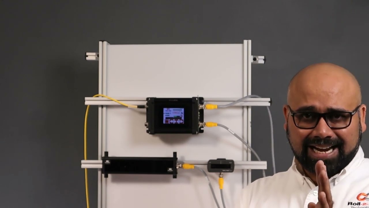
[Music] hello everyone today we're going to take a deep dive into the SCU 6X controller I have a a demo setup here with the um SCU 6X controller in the back and a couple of sensors connected to it what we're going to do is look at the home screen or the main operator interface screen and we're going to look at what are the things that are available in that screen how an operator can use to kind of understand what's going on with the system and also use it for troubleshooting purposes and things like that we have the seu 6X screen right here so I'm going to zoom in to that and we're going to do a deep dive into all the buttons that are available in the operator interface we'll talk a little bit about the connections as well and then I'll finish up with what are some of the common troubleshooting ideas or tips based on the information that is available on the home [Music] screen first and foremost thing that I want to point out is what we call as the heartbeat LED this is basically the bottom left hand corner and this particular LED is blinking between red and green in the SCU 6X there's actually another led a physical LED that's available on the side which is labeled B zero and that will also blink between green and no no light so we call it a heartbeat which means that this is very critical and we want to make sure that this led is blinking all the time so this is again one of those things which is used for troubleshooting purposes if you call us and say hey something is happening nothing is working when we touch the um operator interface the first thing that we're going to ask is that hey is this heartbeat LED blinking and what it is indicating is that there is the program the motherboard is running and the motherboard is communicating back to the operator interface and and the motherboard if there is no communication between the display and the motherboard then this led would stop blinking so that's a good good indication to say that there's something wrong with just the touchscreen operator interface the motherboard is still working fine [Music] the next thing that we focus on is going to be this top right hand corner it says B2 4.2a it's kind of hard to see for you but believe me there is a firware number there so that is basically the firmware number or the firmware version number for this particular controller this is another common thing that you would ask especially for troubleshooting purposes what that fir number and if that doesn't give us enough information we do also have another shmer number on the back which is printed on our product label and that is for if we want to get deep down into it so when do we change these firmare numbers on the top here uh anytime there is a significant change where we are doing a bug fixing we would change that firware number and also anytime there's some UI changes so any anything with related to the buttons adding a new screen or removing a a different screen we would change that firmware number so in general we don't remove any features we only add features to our system so most often if you have a product manual that says version 4.2a most likely it will be applicable to a version 4.1 or 4.0 as well another note if you're familiar with our seu 6X controllers or if you are familiar with roll to roll Technologies we had an seu 5 controller before and now we have the SCU 6 the SCU 6 all start with version 4. something and SCU 5 all start with version 3. something that is the firm number the next thing we want to focus on is this bar right there which is called as the web position indicator and uh depending upon what sensor we have connected the bar will show the position of the web and so for example if I put the web there you can see that it's showing that position and the way the web moves depends upon other parameters but that's indicating the web position another key thing on the bottom left right above that heartbeat LED is called a web detector indicator right now you can't see anything it's gray but when I present the web there it turns green when I take it off it's gray so that is what we call as a web detect indicator when when you are under normal operating conditions that uh should be green all the time I'm going to make it kind of flicker back and forth just by moving the web closer or farther away from that sensor and you don't want that to be blinking like this that's not a good sign and then the first thing that we are going to look at is is the sensor installed properly is there something in the background on the sensor that we need to consider and and is it angled properly so that it's not picking up something and losing the web position both heartbeat and web detect indicator are two important things that are available on the home screen on the SCU 6X we have these two buttons which say sensor one and Sensor 2 and essentially what it is is that these allow us to configure our sensors however way we want our sensors are one-sided which means that we could have the web come in from either direction and this is what we call this a sensor orientation so it could come from this way where it's coming from the right to left or it comes from left to right so our controller can handle either of those conditions we just need to be able to tell it how to do it for all our sensors the orientation is defined this way for the 48 mm sensor there's actually a label that says left and right so if you look at here you would see that there is a right and a left indication that means that if I I pressing a we and I see that left label that means we are looking at the left edge of the web if we come this way we are looking at the right edge of the web and that's how we know the orientation for the 48 mm sensors for anything from 96 to 960 the orientation is this way where that keyb comes out that is going to be our right and where the cable is not present that's going to be our left so this region is going to be our right and this region is going to be our left so if we present the we and we see the left Edge like what I'm showing here so that's going to be configured as a left Edge orientation and if we present the web like this where we're looking at the right edge of the web then that's going to be the right Edge so these bars these green squares are indicating how that particular sensor is Con configured if you press that once it's called a todle between the states I'll do that again so the the four states that are available are no sensor which is what this is both those LEDs are turned off if I press it once sensor one is configured as left left sensor and that's what this is and if I press it another time it will go to Center sensor which means that you have both edges of the web if I press it one more time it's going to go to the right sensor and if I press it one more time I can disable the sensor all together so that's what that button is allowing us to do is to configure the orientation of the sensor whenever we press that button one key thing to note is that if we have this sensor C able disconnect it then this button will only have two states one is enable and the other one is disable because it's either enables the sensor or disables the sensor the controller automatically knows that there's no sensor connected to it so it's not going to toggle between the states it's just going to reable it and disable it so when I reconnect this back in then we have the ability to get all four states right now the sensor is disabled I have it connected now it can go to the left sensor Center sensor right PR disable likewise you can do the same thing for the sensor to and for now I'm going to disable both sensors and just enable right sensor as left Edge the sensor button allows the operator to go from one state to another [Music] state so one of the key things why we have this functionality is that you want the operators to have the flexibility to move the sensor from one side to another side and have a simple couple of steps to switch from one edge of the web to the other edge of the web there are scenarios where when they're running one job they want to write on one Edge and when when they're running another job they want to run on another Edge also we have the reason to enable and disable the sensors because there are situations where they might have two different locations where they are guiding the web and for two different products so for example let's say they are running uh a 20in wi web for one job and a 30in wide web on another job into of moving the sensors from one Edge to the other Edge when the wig changes The Operators can just have two sensors installed at two different cross machine Direction position and then just enable that sensor for that job for one time and then enable the other sensor for the other job at the other time our controller will automatically figure that out whatever the sensor is enabled or how many other sensor is enabled that's what is going to be used for guiding purposes and it will take care of everything else automatically so that's the reason why we have the ability to enable and disable the sensor there are also applications where we have one actuator guiding the web and there might be a scenario where we want to guide the web with one sensor in One Direction and the other sensor in another Direction these are commonly seen in machines where the web can can go both in forward and reverse Direction especially in an unwind or a rewind you can have it configured where in One Direction the the system behaves like an unwind with a sensor installed on the fixed machine frame and then when it goes in the backward Direction the same system behaves like a rewind where the other sensor would be installed in a chasing kind of configuration in those cases we can switch between the two sensors pretty quickly just from the home screen without us having to navigate to multiple screens to enable or disable the sensor so that's the functionality for the sensor orientation buttons so I will present the web right now and we're looking at the left edge of the web and as you can see that the white region in the web position indicator is representing the web and the black region is representing the uh backdown or Mo so as I move back and forth if I have the Lage configured for the orientation then as I move from right to left the web position is going to increase from right to left just like what you see on the scen if we change that orientation to right the bar automatically switches and it goes in the other direction just like what beings right I'm going to disable it and enable this sensor but I'm going to do a center orientation for that this means that we have a a sensor that is wide enough that it can see both edges of the wi the first thing that you're going to notice is that there is a green line in the middle and that line is indicating the center position um of f sensor and when I present a WEP here then you're going to see both edges so that that the left side is dark the right side is dark the middle region which represents the web is going to be white and then the green line is the center line of the we and that's what it's showing there it's being moved from left to right so when we do Center guiding the reference or the edge position for that guiding is indicated by this green line right there so in this case it's Center the controller automatically knows that if you set it in Center then it needs to look at the middle position of the web if we put it back to left mode it's going to look at the left Edge and the green line is still there and it's kind of hard to see but it's at the leftmost point of the white region and that's what we call as um The Edge position so this is what is used for control now in respect to of what we have it does change my Edge position and also notice that I only have one edge of the web or I have both edges of the light break here but it's only looking at the left Edge so when I have this uh small piece of paper where I see both edges if it is configured for the left Edge it will only pick up the left Edge and if I do Center you can see both edges and if I do right it'll only pick up the rage and that's how it works so it doesn't matter if the web is wide enough or wider than the sensor field of you how we configure the orientation will dictate what Edge the is used for guiding or uh control furnaces so there are situations where we would have to use two sensors and uh if the sensor is not wide enough or the web is much wider than our sensors then um we would have that scenario I have this sensor two which is this sensor I have that configured for left Edge in sensor one I have that configured for Frid day and then now if I present the paper that this partly seen by One sensor and partly seen by other a sensor then we're going to see that and then again the the green line indicates the center line position and then the right edges and lighter the left edges indicate the edges of the W one of the things that I want to point out is that in uh normal situations we will always ask that uh when you do Center guiding with two sensors that you use two of the same sensors with the same measuring range and same resolution it just makes it easy and it avoids any confusion here I just wanted to show that it's possible to use different sizes of sensors when you do centri guiding uh what where does this confusion come from just to show on the screen what I mean by that we have one sensor configur to left and the other sensor configur to the right and when we do that the screen is going to be split up into two regions or the web position indicator is going to be split up into two regions if I present the web on just one sensor so I'm presenting it on sensor one which is config as right sensor you can see that only that great half is being updated likewise only the left half is being updated and then when I have a web wide enough it sees both sensors then the portion of the left half corresponding to the left sensor and the portion of the right half corresponding to the right sensor is only going to show up there so the conclusion arises mainly because we have one sensor that is almost six types or or eight types wider than this sensor but we only have the same 50% viewing area on the top so when we move just a little bit on the bottom sensor it seems like it's moving a lot whereas when we move little bit on the top the the right left sensor then it seems like it's moving a little but in reality it's moving the same amount but it's just that on the screen we don't have we're not scaling that based on the two different sensors range so that's the difference so we covered the main things with the sensors in terms of the orientation how the web position is indicated how you get the web detect signal and things like that one other key feature that we have is what we call as reset G point this enables our operators to switch from one width to another width without moving the sensor itself in a traditional application where you have a narrow band sensor that takes about 6 mm that's looking at one edge of the web if you change from one web WID to another web WID then what they have to do is they have to physically move the sensor that's like having a rail and move it there and the other thing that they do is that they might have to do a they they might have a micrometer or a fine adjustment to move that sensor just a little bit based on what the guide point is all of these things could be done digitally from our home screen and that's what I'm going to show show you next to show the gide point adjustment uh I have once in are connected to the controller and enabled and it's set to the left sensor configuration so you can see that when the web moves here it's the left sensor configuration now what we want to do is we want to change the guide point let's say we are running a different job at a different location instead of moving the sensor we want to change the GU point so let for example this is the web and we have traded the web and this is the correct location or this is the ideal location where we want the new reference to be what the game point to be all that the operator needs to do to reset to this gra point is to press that button and accept and that will change the gr point so the gr Point offset on this home screen is showing us how far away from the middle is the current gate point and right now it's exactly in the middle of the sensor speed with view in t zero and Visually it's also indicated by this bar right here and this is exactly in the middle of the field of view of that now if we go to the left of the guide point and let's say this is our new reference and the operators instead of moving the sensor they can move the DAT point so all that they need to do is press the reset G point and say accept now we can see that the DAT Point number moved there and also this dat Point bar move there you know so that one more time let's say they want to use this current web position as the reference then press reset take point and accept and it moves there so this number right here the G Point offset what is showing is that what is the offset from the middle and and that is indicated in the so that's to reset the gate point now if you really want to move the gate Point without the web can still do that by grabbing that and doing that and we call that as a cross gate point adjustment so you can just grab that reference bar and move it to whatever you want and press except and that will do that so that's what we call as a gross great point adjustment and then we don't allow you to change the guide point all the way to one side like that so if we do that it will go only to about a certain amount and that's just for safety purposes and then just to be sure that somebody doesn't intend to do something what we also do is that if somebody press this button and let's say that it it shows the reset gate point to a new gate point and if you didn't intend to do it all you have to do is just leave it alone for a little bit and then that will automatically reset unless you press accept any change to this accidental change it will show that the the current or intended gate point is minus 16.7 but if you don't accept it it will go back to its original gate Point reference whatever you had it for so just to avoid any accidental changing uh we do that and it's the same thing with this reset gate point if you press that button unless you press the accept anything that we do here is not going to change the gate Point unless somebody intentionally says that that's what they want to do we want to make sure that we have everything set up uh properly where we're able to see the web now in the following we will look at how to set up the controller for guiding or actuation the operator can use that uh home screen to put the web guide in Auto put it in manual and also be able to manually jog it left and right and then also do any Servo centering operation or things like that that's what we're going to see next so I do have a couple of things set up here so I have one sensor that is set up to look at the left edge of the web that's shown here since the one is connected and it's set up to look at the left edge of the web and in this particular placee I don't have an actuator connected but I can still show most of the items there through that interface so these buttons on the bottom these are the buttons where somebody could put the webc an auto or manual or jog or Servo Center we'll go through this one by one the Jog and the servo Center buttons or what we call as momentary [Music] buttons this one is basically Auto or manual when it's in red it's in manual mode and if we press it and if it changes to Green it's in automatic mode and um as you can see it's seeing the web right there when I move the web you can see that the web is oscillating here and these are J left and Jog right and then the S Center e