
In this episode of our webinar series on web guiding fundamentals, we dive into the critical role of sensors in web guiding systems. Learn about various sensor terminologies such as range, resolution, accuracy, and linearity, and understand the importance of accurate measurement for effective control. We discuss different sensor technologies including infrared, optical, and ultrasonic, and explore the challenges they face including issues with temperature drift and material properties.
Transcript
Show full transcript (725 words)
[Music] One of the most important parts of a webg guiding system is the sensor. It is important because what you can't measure, you can't control. If you have a poor sensor and you're not able to measure the position properly, then there's no way that we can get the accuracy that we need. In terms of sensor terminologies, range, resolution, accuracy, linearity, those are some things that you would see.
type of sensors, infrared, optical, ultrasonic, air type of things that you're trying to look for in terms of web position. Are you trying to look at edge of a web? Are you trying to look for a line on the web or a contrasting feature on the web? How fast can the sensor measure?
Older ultrasonic sensors have issues with past line changes. You can't have the web too close to the ultrasonic emitter because it might reflect the sound waves in a way that doesn't provide an accurate measurement. And then temperature drift. Again, ultrasonic sensors can have issues with temperature drift when we have the P2 electric crystal frequency changes.
And then what kind of a signal output that you get from the sensor. Range of a sensor is the maximum lateral displacement the sensor can measure. Most often for web guiding applications, range is not that important just because of the fact that you're controlling. You're going to bring it in.
But it does becomes critical when you have web width changes and things like that. Most often range is like how much change in the lateral position that you can measure with the sensor. Resolution is the minimum lateral position change that the sensor can see. So if you want to guide a web to 5,000 of inch, then you better have a a sensor that can have 4x or 2x higher resolution than the guiding accuracy.
Accuracy is an indication of how close the sensor measurement is to the real measurement. This becomes important for certain types of sensors affected by materials. Material properties like opacity, porocity and things like that. This is an important characteristic of a sensor.
Linearity is like what how consistent is your measurement with respect to the actual position across the entire range of the sensor. In terms of sensing, why is it important? Some sensors have issues with material properties like opacity, porocity or reflectivity or they may be affected by environmental issues such as air flow, temperature changes or vacuum. So if we can't measure, we can't control.
That's why sensing is an important part of guiding performance. Most often you would see these type of sensors we refer to as opposing beam or fork style or horseshoe style. There are lots of different names for it. Basically how this works is you have one arm emitting a certain type of signal and the other arm receiving that signal and then the web that goes in between blocks it.
It's a simple technology work sensing principle and it works well for a lot of different cases. The problem happens whenever depending upon this type of sensor signal that you have if the web allows that signal to leak through when it's blocked by the web that's where the pro problem occurs. We talked about linearity resolution range all of those things are affected by this kind of sensor. This sensing signal can be air, optical like visible light, infrared lights, or even UV light.
It could also be sound like ultrasonic. It really doesn't matter. And then whether this material is opaque or porous to that signal is what matters in terms of how well you can guide. Often manufacturers recommend different sensors for different materials and conditions.
So you will have a plethora of sensing technologies out there. Like I said, the main disadvantage is material dependent gain change occurs and then requires calibration if you want to get a really good guiding performance. There are other sensor technologies out there like ours which are not affected by material properties and some of the environmental conditions. I'm not going to go into detail about our sensor technology here but just give you a quick overview.
is basically a high accuracy direct measurement or absolute measurement. Our resolution does not depend upon the range and it can work with any material. [Music]
For a complete overview of web width measurement with Roll-2-Roll® Sensors and Roll-2-Roll® Controller please visit this page: https://r2r.tech/articles/web-width-measurement-and-monitoring-applications-and-technology
For more information about the SCU controller please visit: https://r2r.tech/products/roll-2-roll-controller
Transcript
Show full transcript (1228 words)
continuing along the lines of measuring the width of the web based on the contrasting feature in this video we're going to look at how we can measure the width based on some printing or contrasting feature on the web with two sensors so I've got a sample here with a whole bunch of features on the web not just the edge of the web the left side has a intermittent line of a certain width and then the right line right side has a solid line and then we have some labels with different edges with gradients and things like we can use any of these features to be able to measure the width of the web we don't necessarily need the edge of the web and as explained in the previous video These are relevant for certain applications where you want to measure the width of a coating or the width of a printed feature that might expand or contract differently than the edge of the web and then our sensors have the ability to be ability to do that so let's go into the controller and see how we can set this up we want to First make sure that both sensors are enabled and I've got both sensors enabled and I'm going to the operator sensor screen and we've got the sensor one and the Sensor 2 image as a first step what we are going to do is we're going to teach the teach Sensor 2 to look at that intermittent line and sensor one to look at the solid line and use that information to measure the width of the web so let's go to Sensor One sensor 1 has the solid line so we want to pick that line so I'm going to go in and pick the line mode and pick the feature that I want that's the solid feature that I want logged in on it now go into sensor 2. this is the intermittent line so if I move the web or remove the material you can see that the line disappears comes back in so I'm gonna pick that feature right there lock it in and then we have locked both the features but we don't know the distance between the two features so if we already know what the distance between the two features are then we can enter it so let's say it's eight inches is the distance between the two features I'm going to go in and teach it so the teaching procedure what it does is it teaches the controller to know that to know the distance would be in the two sensors if we don't do that then the output measurement is not it will be it will be proportional but it won't be the measurement so I'm going to go in and teach now I've got that measurement taught in as you can see on the web browser that the measurement now has updated to 8.002 inches and what I'm going to do is I'm going to move the sensor so maybe we can have a picture and you can see it there I'm going to move the sensor so that you can see how that width measurement changes oops there's the width measurement and when I move the sensor you can see that the width increased because I moved the sensor outside and now I'm going to move the sensor inside and you can see that the width goes down this way you can pretty much teach the controller to pick up any feature that you want and have the ability to track the width of the two features and teach the controller for the distance would be in the two sensors and then log the data we'll also look at how we can do the same thing with a different type of feature so we'll go into the controller operator sensor screen and then this is the intermittent line sensor so I'm gonna make sure to try to teach it to the edge of the label so I've got that label there put it on auto and I want to be able to teach that so we want to come in from this direction and pick that edge of the die-cut label there and I'm going to move this Sensor 2 and do the same thing sorry sensor 1 and do the same thing so this is the black line and this is the edge of the die cut label so we want to teach it to that want to go to that mode and pick that edge of the die cut label teach it to that teach it to that we need to make sure that this turns red and all the other features goes away that's when the controller says that the feed feature had been taught if it doesn't happen then the width will not have an output also what happens if we don't have it again if we go back and teach the distance between the two sensors so let's do that to be the same eight inches and if you go back into the web browser then you can see that's the width and if I move the sensor and you can see that on the top right hand corner if I move the sensor then the width increases or decreases so pretty much any feature that we could teach for in the contrast mode can be used to track the width of that contrasting or the combination of the contrasting feature one more thing I want to mention is that we want to make sure that the teaching is accepted by the controller if the teaching is not accepted then the width will not get recorded properly so for example if I go into the sensor screen go in here and then let's say the teaching was not accepted if the teaching was not accepted it's going to look like oops it's going to look like this even though it picked up the contrast the teaching is not accepted and if we go back to the home screen the width is going to be zero this is mainly because that in order to measure the with the contrast mode both sensors the contrast needs to be picked and thought so if we go back in and teach that contrasting feature for sensor one Sensor 2 also has that already and if you go back to the home screen you're going to see the width measurement and if you go back to the web browser you should also see that with the measurement there um that's essentially how we would set up the controller for web width measurement with two sensors and both sensors are in contrast mode and tracking a contrasting feature on either side of the web concludes our presentation about width measurement with either one sensor or two sensors with either Edge mode or contrast mode we also looked at the different outputs that we received from the controller with respect to analog digital and ethernet and with this you would be able to apply our products to a multiple different applications hope this information was useful and please subscribe to our Channel and for more information about our products and how they can be used in your application
For a complete overview of web width measurement with Roll-2-Roll® Sensors and Roll-2-Roll® Controller please visit this page: https://r2r.tech/articles/web-width-measurement-and-monitoring-applications-and-technology
For more information about the SCU controller please visit: https://r2r.tech/products/roll-2-roll-controller
Transcript
Show full transcript (1249 words)
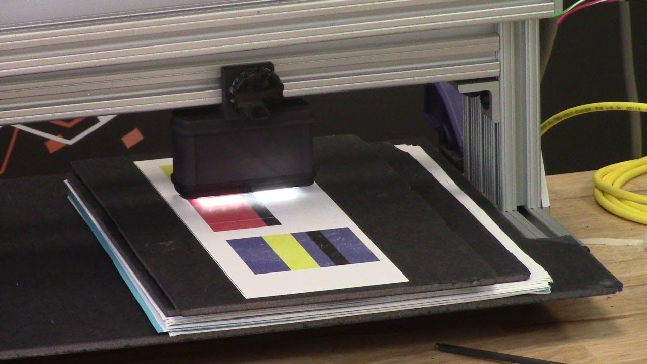
hello everyone today we're going to talk a little bit more about width measurement but this is more like an advanced width measurement application one of the things that you're going to see in the industry is that different people provide width measurement based on the edge position there are certain applications where you would need to measure the width of the web not based on the edge of the web but some contrasting feature on the web for example if you have a lamination or embossing application where you have multiple layers of web and the web goes through some Heating and Cooling different layers of the web May contract or expand and this might change the width of the web and and if you're just looking at the edge of the web that may not be representative of the width change that is experienced by a feature on the web withdrawal to roll our sensors not only can detect the edge of the web but it can also detect some contrasting features on the web and will take advantage of that and with that we can also look at width of that contrast contrasting feature so we have a setup here where we're looking at a sample in the bottom right there and then we have one of our white light sensors the ODC 48 white light sensors installed there and it's looking at that sample and this is just to simulate how we would do a contrasting feature measurement application where the web is stabilized either on a backup roller or really close to a roller so that the plane of the web doesn't change and that's what that is simulating and then we have a controller here and the controller is actually set for contrast mode you can go in and you can see that it's set for contrast mode and then it's also set to provide the width as an output and we'll see how that we can set it up to provide the width output even though we have two sensors connected we have disabled one of the sensors we're only looking at One sensor in this particular sensor is Sensor 2 and it's set for contrast mode what we are going to do is we're going to measure the width of this contrasting feature right there it's hard to see in this image but there is gray region a black region and another little bit brighter gray region here as a first step we're going to make we're going to teach the controller for the feature that we want to this is very similar to tracking so if you want to track this feature you're going to do the same thing press this button to unlock the teaching mode and depending upon whatever feature that you want to pick you can scroll through it in this case we want to pick this black feature right there we have selected it the contrast mode that we have this is the line mode so we have detected that and then lock in on it and if we go to the home screen you're going to see the the contrast the middle of the contrast representing the contrast is chosen as in line mode and then it's also showing the width of that feature so if I move my sensor back and you should be able to see that the width change a little bit but it also keeps track of the position one of the things with this particular mode or line mode is that in order to lock on this contrast there are two conditions that needs to be met one of them is the width of the contrast and the other one is the color of the contrast or the brightness of the and this is intended to make sure that we don't jump from one to another contrast and if you are measuring the width with this particular feature then whenever the width changes too much or the color changes too much you're going to have the measurement you're going to have no measurement what I mean by that is if I go in here and then pick the next line this is still a black line but you can see that the width went to zero even though there is a black line that you see here that's because of it it lost that contrast measuring the width of the web based on this contrasting feature is restrictive in line mode however we can go in and measure the contrast with in in other modes for example if you want to look at this particular width so this is the width of this region that you want to measure you can select that teach it then go to the home screen and that's showing you the width of that region and if we reduce that width you can see that that this region is 0.68 inches and then if we move further and further that region increases and it'll go all the way up to you see any other black region and now this is the measurement of the width the contrasting feature width and if we move any further the width is not going to change because it's bound by from this region to this region so we can not only measure the edge of the width of the width based on the edge we can measure the width based on any of the contrasting feature in the web so this is with one sensor how we do it some examples of applications is to measure the width of a die cut edge of a label to the edge of the web this is important in slitting certain slitting applications require the edge of the web to be at a certain distance from the die-cut edge of a lab or edge of the web to be at a certain distance from the edge of a printed mark on the web other applications are to measure the coding width in any type of coding or glue width or any of those kind of things lithium ion battery trim width measurement or tab width measurement or some other examples of this application where you want to measure the width of a contrasting feature the outputs that we provide is going to be very similar to the edge outputs so in this case we are using a 48 millimeter sensor and then this value is or we are using about two inch wide sensor and this value is about 0.68 inches so the output if it's an analog it's going to be proportional to the width of the sensor and again you can also get this output through the ethernet and if we look at that on our web browser we should also see the same output so again if we look at the output on our web browser it shows 0.685 inches and if I move the sensor and the width changes it updates that value again you can do it in millimeters if you want that's 21.7 millimeters or in inches it's 0.805 0.855 millimeters okay so that's a quick overview on width measurement based on a contrasting feature on the web with just a single sensor in the next video or in the subsequent video we will take a look at how we can do width measurement with two sensors based on the contrasting feature on the web
Transcript
Show full transcript (1112 words)
Hi, I'm Pedro Velasco with Rollto-roll Technologies. In a previous video, we showed you how to teach the SU5 controller for contrast sensing applications. Um, well, today we want to talk about a little bit about one of those applications, which is line guiding. Now, converters in specifically uh slitter uh slitters uh will actually find this information very useful.
Uh we have a different way of looking at line guiding. uh mostly because we realize that there are possible savings to this and there are special situations where uh converters might find it difficult to guide a material on certain contrasting features. So uh let me go ahead and switch over so that we can see both the screen of the SU5 and our WPS uh 48 sensor white light sensor that we use for uh uh contrast guiding. So in this case we have a uh the SU5 screen on the main screen and then we have on the right upper side the uh WPS48 white light sensor.
Now, when we're looking at typical line guiding applications, we'll see something similar to this where you're just looking at continuous line uh on a printed on a web. Well, we can actually eliminate the need to print that line and uh help you in saving money from having to print additional features on your web or even by reducing the width of the web. So, one of the things that we do is first we have to go through a teaching mode where I can show you what are the different uh ways of line guiding that we have. Our most typical way is just consider something as a line.
In this case, I have set up on our sensor a black line that is shown right here with red and white on the side. If I teach it to follow that, let me go back. Forget if I teach it to follow that. And then that green line right there tells you the feature that it is following.
So, as I move this around, you can see how the sensor is capturing where that line is at. Okay. However, what if we have a special feature such as this? We don't have a printed line, but we do have something interesting.
Our technology allows us to use the white space in between the labels here so that we can consider that as a line as it goes through. If we go into our teaching mode, we just maintain that same line, but then we say it tell it to move to that space that we wanted to follow. And every time it sees that space, it will capture. Now, right now, because I'm moving this by hand, let me find a better ride there.
It will capture again every times it sees it. Right. Of course, the the uh the web has to be very stable when it does this application or any application of line guiding or contrast sensing. One of the beauties of this is that we don't rely on the information from the operation such as uh web speed.
The controller and the sensor do all that for us or do that all for you. And in this case, every time it sees this, it sees the contrast that it's following, it will guide the material to that pos or it will guide the material to adjust for that position. And when it it loses it, it stops the web guide at its last position. And then every time it catches back on, it moves the web guide or allows it to move.
So that is one uh interesting feature. However, what about if you have a feature such as this one right here where you have labels that are irregular on one side, but they're a straight line on the other side. Well, we can use the same concept of guiding on that negative space by using this right here as the edge of a line right there. Right?
We do have that application here when we look at it. and we say let's look at that web and let's look at that feature right there but coming from this side. So as you can see this is the black space of the board right here. This is the white of the web right here and this is where the label starts to be.
So these are different features inside the label but we wanted to follow this particular line right there. So we teach it to go follow that. We in uh identify it right here with a with by moving with the arrows to the feature that we want. Then we accept that.
And as you can see there's a green light the green line that tells you that is the feature that it is following. And as it goes from label to label it just keeps on falling. Same condition as the other application. Whenever it loses it, it stops the web guide and when it catches back again, it activates the web guide again.
Now, another one that we have is where we look at two contrasting features which can be shown by this right here. So, let's say I am interested in following wherever there's the red and the black. So I can actually teach that position and I do it by selecting this mode right here. And then I go and look for that condition right there.
Accept it. And then you see the green light right there. The green line where it meets the red meets the black. And wherever it sees that it will follow it.
Now if it goes to something that is different than that it will lose track of it. But once it sees it again it will again continue to monitor that position right there. Right. So those are the features that we have for contrast sensing for specifically the line guiding application.
Now, we have other ways of dealing with contrast sensing and line guiding. If you find this information useful and would like to know more, just contact us at r2r.te. Now remember, we have applications that allow you to follow a uh a line that is not continuous and doesn't require to do any specific setups on your line to feed information to our controller. Our controller works on its own.
If you like this video, just give us a like on YouTube and uh we hope to that this has been very informative for you. Keep a lookout for other videos that we will presenting in the near future.
The webinar will cover sensing and measurement technology that are used in Roll-2-Roll® Sensors.
The presentation will cover:
- the fundamental working principle of the patented fiber optic technology
- how it differs from the conventional sensors
- benefits of the fiber optic technology
- application of the fiber optic sensor technology for sensing and measurement applications such as edge detection, width measurement, registration mark detection, flag detection, void/hole detection, tear detection, etc.
Transcript
Show full transcript (9115 words)
talk a little bit about the different sensors that are available in the market and how our sensor is different and then we'll also talk about what are the applications for our sensor in this industry so to start off with just to give you an idea on some of the topics that we cover most often when we are looking at edge sensing a lot of the sensors that we use are going to be optical sensors but the some of the concepts that we have covered here doesn't really only apply to just optical sensors it can also be sound or any kind of a wave so some of the basic concepts that we are going to be looking at and is what is reflection what is absorption what is transmission and how the conventional sensors use these concepts to determine the web position and while we are going through this presentation you will also have some polls that will be administered you should be able to see the pulse and if you can answer those that would be really helpful for us so that it cannot guide us through this process I also have Carlo and Pedro Manning the polls in the Q&A section so any time there is some question or things like that feel free to put your questions there and they will be able to address that so in terms of concepts let's take a look at these so reflection so we have a light source that is being incident on an object and what can that light do well basically there are three main things that can happen to the light source the light can be transmitted through the object most of the time if the material is optically transparent or translucent there is some amount of the light or radiation for that matter which actually goes through the object some amount of light would be absorbed when the light is absorbed this is mainly because the photon the photons interact with the object and they would get absorbed into the object and this may be dissipated in the form of heat or even fluorescence then some amount of light would be reflected and basically the reflection is whatever the light that is incident on the object that is returned back to the same medium that is called as reflection here the the object is usually a different medium it could be a solid it could be a liquid whatever it may be and then where this incident light is that's another different medium it could be air or it could be vacuum or any of those so the reflection is basically returning the light back to the original medium transmission is basically passage of light through the medium an absorption is actually absorption of the light into the medium the reflection and transmission typically do not change the light frequency when we say frequency it's more like color so if you have a red light and the light goes through an object or it gets reflected the color typically does not change there are special cases when it will change but usually it doesn't change and then absorption is basically the light is absorbed into the material and sometimes the absorbed light will actually change the state of the material and it can cause further emissions and those are called fluorescence these are something that you would see with ultraviolet light source and when they fall on a certain type of object the object actually absorbs the light in the ultraviolet frequency range then that absorbed material gets to an excited state and then that emits a light in a different frequency usually called fluorescence so most sensors use or most optical sensors use these these three phenomena to kind of figure out how to detect the web so actually how it happens is is based on the amount of light that is transmitted or reflected or absorbed and there is a term for those and that's called reflectance which is the ratio of the light reflected to the incident light transmittance is the ratio of the transmitted to the incident radiation and an absorption is the ratio of the light absorbed to the incident radiation the reflection reflectance and transmittance or usually used to define optical properties of material so if a material is optically transparent that means that it transmits a lot of light through the object or it also reflects a little bit of light through the object that's what it means to be an optically transparent material while on the other hand if a material is opaque that means that the the object is going to reflect most of the light and it's going to transmit very little if not none of the light that is falling on the object so most often I mean almost all cases the color that we perceive on an object is because of selective absorption so if you see an object to be green that means that that object absorbs all bay links of light except green which is reflected out and that's why we are able to see the object at screen now all of these depend upon the wavelength of light certain objects behave differently based on the wavelength of light a great example is x-ray which is also a radiation x-ray may pass through opaque objects which are opaque the visible spectrum but are actually not opaque in the x-rays wavelength like wise and transparent object may not really be transparent in a different wavelength such as an infrared that's one of the reasons why our infrared sensor can even work with transparent webs transparent materials so these are the basic concepts in terms of how light interact with an object or what happens when light falls on an object most sensors use this principle so this is one of the most common sensor used in edge detection and it's called an opposing beam sensor essentially what it is is that the sensor has got two sides to it a transmitter and a receiver the transmitter sends some kind of a signal could be light sound or it could even be air just for our case we will just limit it to light and sound and then the receiver and in in the end and that signal is being transmitted or absorbed by the material and then the remaining signal falls on the receiver so this this technology or this sensing principle works well when the material absorbs the light or the signal like what we have shown here so none of the light sources that is falling on this web material is actually transmitted so you can basically infer the position by looking at how much light that I get or let's say if the receiver gets 50% of the light then it means that the web is at 50% of the viewing area that's where it is it's really simple sensor technology and usually it's also referred with different names it's called fork-style or a u-shape sensor or a blocking and unblocking sensor technology now like I said most often this sensor technology works but there are some cases when it does and work well and as you can imagine whenever the web material starts to have high transmittance then the signal is going to leak through it and the sensor will provide a different output now if you compare these two web materials they are exactly at the same location but because of the properties of the material you're going to have different transmittance and that really affects the sensor output and that's the main shortcoming of these types of material now how does it how does it involve how does it relate to our cases basically if the material is porous that means that actually there is no solid there to prevent that light to go through or sound to go through then that's a problem obviously if it is opaque sorry um the opacity is lower then that's a problem and this means that the sensor requires calibration and since this is an inferred measurement let's say you are you get 50 percent signal that means you assume you're at 50 percent location this is not an absolute measurement so you really don't know unless you calibrate it what the actual position is and it's not accurate that's the main thing with it there's also ambiguity in spatial ambiguity with this kind of a sensor sensor technology I'll talk a little bit about it in the next slide about what what I mean by that now there are other types of sensors that try to avoid the issue with transmittance and the way they do it is what is called as a retro-reflective sensors you have a transmitter and receiver on the same side there is no receiver on the opposite side the light is now incident on the reflector the reflector is a special material so it reflects the light back to the receiver and when we do that the portion of the light that goes through the material is attenuated here and then it falls on the reflector and now all the light that is falling on the reflector is reflected back to the receiver and the light that actually goes through the material it's actually attenuated twice as much as if you had a transmitter and receiver on these two sides so the main advantage with this kind of a system is that you are essentially doubling the or essentially reducing the transmittance by half by making your light go back and forth twice through the same material so if you have like an clear material you might be able to do this where you can increase the sensitivity of your system and then you can you can use the retro-reflective technique to detect the web the other advantage of this kind of system is that the transmitter and the receiver are on the same side and then the reflector could be much farther away from the transmitter and receiver so that essentially make this like a one-sided system and this has other advantages in terms of like you don't have to have a constrainted fork where where the the throat of the fork you don't have to worry about that if the web plane changes and things like that and it's usually compact most often these retro-reflective sensors are used for in presence/absence detection and there are some sensors that are used for nonwoven applications and they actually use a special mirror kind of a thing so that it can go through low basis weight nonwoven a couple of times before we can get the signal back so that's a retro-reflective sensor now the main thing with the conventional ed sensors is that it's a simple sensor technology when you have low transmittance but as soon as you start looking at materials that have special properties and things like that these sensors have issues especially with engineered materials like nonwovens and and some really clear material the material properties affects transmissions and absorption and hence the accuracy of the sensor is lost now I talked about spatial ambiguity let's say the receiver is a single element maybe it's an ultrasonic receiver with just a one element or maybe a photocell if that's the case then if you have a small object like this which is much smaller compared to the viewing area of the sensor and if the object is anywhere within this range there's no way the sensor can tell you what the position is it can tell how much signal attackin teammates but it cannot tell what the position is and that's what is called as spatial ambiguity with these kind of sensors these are especially important when we look at threads and things like that with our sensor that's not an issue the other thing with these sensors is it cannot detect surface characteristics so it the the whole web either blocks or transmits and since there is no way we can figure out if there's a feature on the web or a structure on the web there's no way this sensor technology can detect what it is the other issues that these technologies have is that image saturation issues basically what it means is that most often the receiver is saturated by light and then you have a let's say you have a small object that is there that photo cell or the pixal for that matter might be saturated and it would have some kind of a saturation issue with that so when you are trying to detect a small object or a feature there is a problem then finally the sensor resolution and depends upon the range of the sensor so if it is a single receiver element and you want to make this sensor 2 inches wide then the resolution that it can detect is going to be the same as set a solution of the A to D converter or whatever it may be so irrespective of the width of the sensor or the range of the sensor the resolution would change and that's an issue now instead of using transmittance can we use reflection of the web to measure the web position and the answer is yes we can and that's what we do with our sensor and in order to look at that let's take a look at a few concepts about basically reflection or scattering or diffuse reflection and a couple of different things that we use in our sensor technology and then our sensor is based on optical fibers and optical fiber properties or fiber optics so we'll look at a couple of concept there as well so again we have an incident light that is falling on an object and we talked about reflection transmittance and absorption actually this reflection was just like a simpler way of representation of the light the light source is going to be it's not it's not going to be like a ray it's going to be a wave in fact so what really happens is that the light falling on the object it's actually scattering everywhere and the light goes off everywhere and then there's a portion of the light that is reflected now this phenomenon where it scatters off everywhere it's called scattering or the actual technical term for that is diffuse reflection and then this ray right here which is following the typical ray optics is called specular reflection so you have specular reflection and then diffuse reflection specular reflection is usually seen in smooth surfaces polished surfaces mirrors and things like that where the light will bounce at the same angle as the incident angle and scattering and diffuse reflection is going to be seen in most materials that are not polished or smooth so almost every material that we deal with is doing the few scattering and the reason why we are able to see a color in an object on an object is because of scattering or diffuse scattering so the the reason why this is scattering in all these direction is because the surface has got irregularities on it and those irregularities have different angles and when the incident light falls on that microscopic irregularity its reflecting it back at the same angle with respect to that small microscopic surface but because we have a whole bunch of those the light is scattered in all the different direction just like scattering and reflection there's also diffuse reflection and regular sorry diffuse transmittance and regular transmittance when the light goes to it and that is not of importance for us the main thing for us is this reflection now there is another thing that is important when you're installing the sensor we talk about the angle this is mainly saying that if you have a light source that is coming at a certain angle then the maximum amount of scattering is going to happen close to the normal when we do our sensor installation there are some sense of installation recommendation that we provide that's that's mainly based on this so if you have if you want to view the object from this angle then as you can see here there's going to be a lot less light than if you view from here and likewise the light source as well this is called as Lambert's cosine law and basically you want to keep that angle as close to normal as possible so that we can get the maximum so if we use scattering how do we make a sensor that can do this again and just like a retroreflector one we have a light source and a transmitter and a receiver the the light goes through here falls on the web if the web material was perfectly reflective then all the light that goes here will exactly reflect back at the same angle which is normal to the surface and then we will have a really good image and we'll be happy but that's not what happens the light when it falls on the material it's just chaotic it's going to reflect everywhere or scatter everywhere and we're going to have the same issue like an opposing beam sensor technology where we have scattering and which will be dependent upon the material and how far the material is from the web and and the spatial ambiguity and accuracy and things like that so how do we fix that basically we add a filter to it and that's our proprietary technology so we add a filter that filters the light and the way it works is that when the light falls on the web it scatters everywhere but the filter is going to selectively couple the light coming in falling on it at a certain angle and now the light goes back now we know where the web is if this receiver is a pixel array or some kind of imaging element then we would know all these elements would receive light and all these elements would be dark and if we do an edge detection algorithm we can figure out where the web is that's the underlying principle of that and how do we create a filter that's based on fiber optics so optical fibers have special properties in that they allow the light to go in only at a certain angle like the cone that is shown here so if you have the web if you have the light falling on the fiber at an angle that is steeper than the scone it will not go in so it's basically gonna filter out all the light and allow light only coming at a certain angle to go in and that's how we do it so that's the basic fiber optic technology that we have so how does it work just to give you an illustration there's a light source that is illuminating the web and the light scatters everywhere but then the light that is directly underneath the fiber is the one that gets coupled into the fiber all the other light that is coming at an angle doesn't get coupled into the fiber and that's how we we we didn't mind what the web position is again this is a true and absolute web position measurement because the fiber has to align with the web edge for it to be able to pick up the light and just just an illustration of how we do it now essentially the light source angle can be at any angle as we saw before but we want to keep the scattering to the maximum so we're going to keep that light source as close to the receiver as possible to take advantage of the Lambert's in my inverse Lambert's cosine law so we have a light source it could be laser LED or anything like that it falls on the surface it scatters everywhere this is a side view of the optics and this is the front view of the same thing so the light falls onto the fiber optics and then the photo diode or a pixel which is position behind the fiber optics is going to pick up that light that's how we determine where the position of the web is now I mentioned that we have a pixel or a photodiode behind the fiber basically what we do is we capture the image and then we do real-time image processing to determine the edge of the material this is an important part of our sensor technology technology not just that not just the the way the sensor works but also how do we process the image is important the algorithm adapts to a few other things that we will talk about later in terms of how do you adjust for intensity changes how do you adjust for focal lengths and stuff like that so essentially a component the components of our sensor or four main components one is the light source we typically use LED light source it could be visible or a broad light spectrum or infrared or even UV light and then there is an optics that is filtering the light that is coming at all different angles that is our patented fiber-optic technology and then there is an imaging element behind that optics which is usually a linear pixel array and it's anywhere from 768 pixels to about 14,000 pixels and these pixels are arranged really close to each other at 63 and 1/2 micron or about five thousandth of an inch and then finally the image processing algorithm which actually does the edge detection so let's see how that works now we have a different samples of web that we can present to our sensor as you can see the some of them are opaque some of them are completely optically transferring some of them are porous they have voids in them and irrespective of any of those our sensor can provide a really reliable and highly accurate web position measurement I think this is a published article that you can find in converting but the but dearest the accuracy was about ninety over ninety nine point three percent with any of those materials and we didn't do any calibration that's the main thing with our sensor technology now just to give you an idea we saw the different images as you can see the light that is falling on to the imaging element is going to have varying intensity depending upon the material that we have so if we have a light scale where blue is completely dark and red is completely light or white and then there's a spectrum going through that you can see that all of these edges are are not as sharp as what we have illustrated in the working principle in spite of that this is the output of the edge detection algorithm they did the edge detection algorithm goes in and says oh this is the edge for this black nonwoven web this is the edge for the transparent web this is the edge for the load GSM nonwoven and this is the edge for the perla now we don't really just have to look at the edge of the material we can actually look at features or patterns on the material as long as the pattern is parallel to the machine direction then we can do the same thing so here for example we had some die cut edge of a label so we wanted to detect the edge right here edge right here edge right here on the edge right here so and again we can do that with our sensor technology and it provides a pretty good measurement so in terms of the the image processing feature that we have the key things there are we do what we call as dynamic threshold that means that every single image that we take every sample we do run our edge detection algorithm and it automatically to the lighting it adjust automatically to the focus it adjust automatically to the material and figure out figures out where the edges and just to give you an example again this is an image from our four 440 sensor with infrared light source black just means that there is no light coming back and then white means that it's coming back now this is the raw image on the top we presented a burlap web right there and if we just say I don't care about what's in between I just need the edge of the web tell me the left edge in the right edge then we can give an output which is going to be like this so the edge detection algorithm goes in and picks up the left edge in the right edge it doesn't care about anything in the middle now what happens if we have a lower brightness it's the same web same location we have a lower brightness as you can see these two images are pretty different with low intensity again no problem no setup no calibration the edge detection algorithm will automatically adapt to that and pick that and what happens if you have a really bad image where it's not only low brightness but it's also further away from our sensor no problem we can still do that I'm not sure if you can see this on your screen but this is really faint gradient here but we can still do that now the other things that we can also do is background suppression what it means is that we have special way of adjusting automatically so that if there is a background in the image which is at a certain distance from the web we can still adjust for it and that's what is shown here so here this is an example of a clear web with an infrared light source on it and there's some background there and we were able to automatically adjust it and provide the edge positions there now when we do this we also have additional information that we provide from our sensor we can provide an edge quality feedback that means we can say how good the edges we call it as a quality factor we can provide it for each edge that we measure and then we can also provide a flutter feedback for each edge again the quality factor is based on instantaneous measurement while a flutter is based on temporal it's a function of time so but anyway we can provide that flutter information as well now other things that we could do is one of the things with the with the conventional sensor is that it has issues with spatial ambiguity this is going to be common when you have like really small feature our sensor obviously does not have that issue and just to give you an example here is an image of a single thread this thread is like two or three millimeters wide and we can pick up a single thread like that with our sensor and and what if you have multiple threads and let's say you are running some kind of an operation where you have to guide or bring in multiple threads into your process and you want to be able to count the threads well if you present something like that we can still do that as you can see in the raw image there are some threads which are kind of out of focus or farther away some really in focus and a it doesn't matter our algorithm is able to go in and pick that up and tell you process the image and tell you the edges now when we do edge detection like this we can essentially provide you with every single edge position where they are within the sensor or most often because it's a lot of data that is going through we can actually provide you some statistics of this whole measurement so we can say well what is the average width of these threads that we picked up and what is the average gap between them so on and so forth what is the minimum what is the maximum so we can compress that in the data and provide some statistics that you can use to kind of figure it out like for example here these there are actually two threads here these two threads are really close to each other and when they are close to each other then this kind of the thread kind of became like double so if you're able to monitor that then we can figure that out and tell you that hey something is coming too close to each other or overlapping and things like that again we can with low brightness it's not an issue we can still pick up that edge right there now I talked about edges but it doesn't have to be an edge here this is basically a printed pattern that we are looking at different colors different colors are going to reflect light at different intensity again an infrared light source is illuminating a colored web here and you can see that it can pick up these contrasts so when we do contrast application what we can do is we can not only tell you the location of the edge where the the contrast is different but we can also tell you the intensity of that so that's how we can teach our sensor to follow a particular color or a line or something like that now we we have done sub-pixel edge detection so that means that we can go to one twenty thousandth of an inch or sixteen micron in terms of the resolution our standard pixels or the standard imaging element has a resolution of 63 and a half micron and we can do 1/4 or 1/8 of that to get sub pixel resolution so those are the features of our sensor in terms of the sensing principle how we do image processing and how the raw image looks like and how the process image looks like and things like that now let me just quickly go over some of the applications that we have with our sensor first and foremost we do edge detection that's one of the basic things if we want to do edge guiding then we need to do edge detection the other things that we do are with the measurement contrast position measurement contrast position detection and contrast our pattern it's pretty much the same kind of thing then we do thread counting and I showed a little bit about that we can also detect a mark on the web we can also detect a flag on the web we can also detect what we call as a coverage or the for lack of a better term optical density of the web and then finally the stack measurement so let's go over some of these really quick edge detection since our sensor is one-sided you can have a web that is coming from left to right like in this case or from right to left it doesn't matter all we just need to know is what direction we need to scan for the edge if if if the sent if if the sensor if we're looking at the right edge of the web which is this one then we're going to scan from right to left if we're looking at the left of the left edge of the web then wicker we're going to scan for from left to right now what we are going to look for is in an edge detection is the first transition from a dark to any kind of a light and that's how we would do the edge detection now I've got a short video here and hopefully it can play properly and these videos are on our website but the idea here is to show that we can put any web material and this is showing the position of the web we can pretty much put any web material and without any setup or calibration we can get the true measurement or the absolute measurement of the web this is like a highly porous non woven that we used the other extreme example is like a really porous mesh kind of a web even if we have a web like that when we do edge detection we can accurately get the leftmost edge of the web or whatever the edge that we want we can get that accurately so that's what this video is showing so some application example where we provide the most value to our customers is that whenever you are doing edge detection with frequent material change over like if you are going to detect a paper web all day every day yeah we can do that too but that's not where our value is this would be like nonwovens or any any kind of engineered material that you are changing quite frequently where you don't know the opacity and the porosity and stuff like that our sensors work great in those application or if we do width changes like I mentioned we can go from about 48 millimeters up to about 900 millimeters in sensing range without losing any resolution that means that you can run different webs without different width webs without needing to move the sensor that's another place where we have a pretty good advantage challenging materials of course that's that's our specialty is if you have something that's really complex then we can do that and then challenging environments specifically vacuum that's a place where we have got a lot of success especially when we are trying to detect clear film inside a vacuum environment now the advantages are that we don't need any setup for calibration and it's pretty cost effective in terms of connectivity we have industrial Ethernet this could be Ethernet IP or pro finet will also have EtherCAT and other things that we could do as well and some unique applications like I said clear web inside a vacuum this is pretty unique just because of the fact that most current technologies for detecting clear film or ultrasonic and ultrasonic doesn't work inside vacuum so that's pretty unique for us and then again metals that's another place where metals inside vacuum is another one since our sensor is single sided we have successfully used our sensor in abrasive environments where a web flutter or something like that they typically knock off a fork style sensor and we can position our sensor farther away from the web because our algorithm can adapt to that and we were able to do that with an abrasive web environment and then you can also do width measurement on low basis weight non-roman this is usually a problem with current sensors because they are not they're really really you need to do a lot of filtering with that or it could be some kind of an edge that is kind of ragged and we can also do like detecting ridges on a web so this could be some kind of an extruded plastic or something that has got a three-dimensional structure on it and you want to follow or see that some of those things we could do just to give you an idea the the the the sensor itself has just the optics the imaging element and the light source it doesn't have the processing so you need a sensor and a controller to do that it shows and then different output options at the hint we can have for edge sensing usually we can to analog output if you want to connect it to some legacy systems that use analog sensors otherwise we prefer to provide Ethernet IP or Pro finet for that matter option for H as output now the other common application that we do is width measurement now width measurement with two sensors or one sensor obviously this sensor is too small and if the WebWork changes then you're going to have an issue that's where we have our value where we can provide a wider sensor and what you don't have to have the sensors mounted on some kind of a linear positioners mechanical positioners these are again cost prohibitive and have inaccuracies and all those kind of things so you can avoid all of those by using a wider sensor and when the web which changes the sensor doesn't move so it can still detect the web width now if the sensor is wide enough then we can measure both edges of the web with a single sensor again this having a single sensor that does all of those then you don't have to worry about alignment the distance between the two sensors and all those kind of things this is the reason why we are moving to wider and wider sensors every year and we are about to release our 900 millimeter wide sensor this summer anyway if you have a wide sensor then you can see both edges of the web and without having any issues now most of the time these are applications in shrink sleeve so this is a one of the video from our distributor in Mexico but as you can see one of the things apart from providing accuracy and resolution in width measurement it's a safety thing so you don't really have to have somebody go in and measure a web while it's moving to make sure that it's at the site the correct width you can have an automatic automated system that can do that so here we're showing our for 40 mm sensor that is looking at both edges of the web in a shrink sleeve or a folding web application now we can do the same thing for others and some of the common applications are if you want to look at a blown film and you want to measure the width of the tube lay-flat width of the tube of the blown film a lots of different applications again this is one of our videos from our distributor in Mexico so like I said width measurement where we see it where where it's used like any time you are slitting and let's say you're slitting something that is uh that that requires you to measure the width to verify that we can use that folding the web again it could be in swing sleeve it could be other folding web applications and sometimes you can also look at the trim width just to make sure that you don't run too far out to the trim I mentioned about blown film and then extrusion like you can use it for monitoring extruded webs like resealable zippers or things like that that's where we we have our sensors installed and then you can also look at like width of tire rubber and in that case we can we actually have it in a back roller and we can do that as long as there is a contrast difference between the edge of the web and the background it doesn't have to be a clear background or a free space it can be anything then we can do that again different output options we typically prefer ethernet/ip or or or some kind of a industrial Ethernet apart from looking at the edge of the web we can look at contrasting features so basically we're taking advantage of the fact that different colors are gonna scatter light at different intensity in this case we are showing a white light a white light is typically used when we want to bring out visible contrast it doesn't have to be white light it can be UV so that you can have a fluorescence or can be IR as long as you are able to see the contrast difference and the light source is mainly used to extenuate the contrasting feature so either depending upon the frequency of the light source or sometimes the angle as well so some applications would be like if you want to look at a coated edge and you want to see how far the coating is to the edge lithium ion battery or any kind of coating that you can do even just regular paper coating you can do that and in paper coating case you would probably use a UV light so that most often that coating on the paper has some UV fluorescence to it or it can also be like looking at maybe tabs or things like that on a conveyor we can do that too and then not only are we detecting the contrast we can also provide the position of the contrast so you can use it for control purposes as well I've got a couple of videos here but I'm gonna skip that and you might be able to see that in our in our website I think I talked about this quickly so anytime you are guiding in a slitter where you want to slit to a printed line that's an application that could be in a doctor machine as well if you want to follow a UV line then cording width measurement and then some other simple inspection applications here's a quick video where we have a application where our sensor is installed to look at this bag which has an extrusion which is clear and then the bag itself is opaque the the idea is to measure the width of the green part of it and disregard the clear part of it and we are able to do that in this case it was installed with the free space at the back but it doesn't have to be free space you can actually install it with the back roller on it here we have an example of our sensor used to detect the width of the web where the web is supported on a roller and there is a contrast difference between the roller and the web and it's it's not clear here but we use a white light source in this one and we're actually looking for the edge of the clear film and not the edge of the printing and with the light source and we can do that and this is made this one is for width measurement for detecting wrinkles so whenever you have a wrinkle on the web that's going to reduce the width wrinkle or a fold over that's going to reduce the width and we can use our sensors to measure that there or like I said in the other application would be like if you have a tire width measurement application you have two sensors that are mounted and it can look at that the tire and in this case they they were kind of a little bit creative about it and they put a background that is white and then the tire by itself is black and the reason why it's black it's because it's absorbing all the light so in order for us to detect this we need to have a white background and then and then a clear a black foreground which is our web then we were able to detect that so that's our common width measurement application I briefly went over this this is another thing that we do is like string thread fiber monitoring so it could be like things that you use in textile and waist bands or or carbon fiber applications where you want to accurately measure multiple webs and in this case we would be able to do measure and count and provide statistics on what is the minimum what is the maximum what is the gap so on and so forth and we can also provide additional information like that again I'm going to skip this video for the sake of time and like I mentioned it's elastic thread or textile or carbon fiber any of those the main advantage here is that we're replacing some camera based system with our sensor and then for thread detection we are replacing mechanical pulleys and and pressure-sensitive sensors and we can actually stitch together multiple sensors over Ethernet our 440 sensors we have installed it up to 2 meters wide where we have connected four of them together which is possible the next application is marked detection so again we're trying to look for a contrasting mark which is a which is going to have different scattering and we can do that the main difference here is that the mark is along the machine direction sorry if it's it goes faster it's not a consistent mark that comes and as in a printed pattern or things like that but it doesn't matter we can still detect that and it can be a visible mark or UV fluorescent mark any of those and it's not only that we can detect the mark we can actually track the mark in terms of position that means that we're not just saying giving you an on-off signal we can also provide an analog output that tells you where the mark is with respect to the sensor the main advantage there is that we have a wider sensor so if the web moves we can still track the mark we can also detect flags on the web so let's say you have a web and it's got multiple flags you are going into a slitter now you're going to remove all the flags and then you're going to another process and then you want to put the flag back in how do you do that then you can detect a flag and then have some kind of a thing that would put the flag back in again after you complete it this is a little bit even though that you can see that the flags are different colors different weights different sizes the web may be different we can do all of those without any need for teaching I can adapt to different flags and different webs and it is not affected by web wander or web moving back and forth then we can also provide a quality signal in that case we can also do tear detection or coverage this is just an illustration or example of let's say there is a tear in the web and then the web actually splits we can detect that this is an exaggeration but if the tear is small we can still do that now if the web separates and moves the left and the right edge moves then that's an easier one to detect but if the web's doesn't move and you just need to see a wide or a hole again we can detect that again all of this is based on how much light we are getting when there's nothing when there's a wide or a hole or a tear if this region is going to be dark and this region is going to be white and then we can basically integrate how many pixels that are white and how many pixels that are black and that gives us the coverage and by monitoring the coverage you can detect if there's a hole or tear or anything like that one other application that we do is we could do is also product linked measurement basically what we do here is we just rotate the sensor 90 degrees and when the product is moving on a conveyor it can track the edge and it can basically say how wide the product is the main thing with this is that the sensor doesn't have to be longer than the product and then the product can run at different speeds and you don't need an external synchronization signal to be able to pick up that so that's a quick summary of some of the applications that we have just to summarize the advantage of our sensor technology is that it's accurate it's got it provides an absolute measurement it's very simple to use when you compare to like a traditional fork style sensor or maybe even a camera based sensor the resolution is not affected by range in a camera based sensor if you want to have a bigger range you have to install the camera at a certain working distance and when you do that you lose the resolution we don't have to worry about that in our case and it's a one-sided sensor so like in a camera based system you would have to install the camera or the light source the gantry all of those here it's all enclosed fully contained and because the sensor is going to be close to the web we can have a pretty good lighting control and then it's also compact in terms of installation and we have done a lot of customizations for our sensor and these would include processing speeds of up to about thousand Hertz and then we can track multiple edges there's really no limit to the number of edges we can track it's just that the information how do we send it and then sub-pixel approximations I mention that before two to eight X we can do that and we can also control the edge detection through Ethernet industrial Ethernet and then light source customization based on the application and then essentially the customisation is bringing us more and more close to a line scan camera based system but at a much lower cost and the difference is that we actually do the customization and we don't just sell the the the sensor and the imaging we actually do the processing as well unlike other line scan based systems so that's essentially my presentation and here is the contact info if you have any questions or any application or any need for sensors please let us know and I do have some questions in the Q&A section so let me just quickly go over some of those and see can your sensor technology by the way please use the Q&A section to ask any questions if you have can your sensor technology also measure a webs thickness across a sheet of material while in motion if if that's true what when a number of threads are being read in addition to placement of threads in their respective spacing can you also read the thickness yeah the the thickness we can't do that right now not in the current state we can look at what we are doing is we are taking a projection of the image a actually it's a 1d projection of the image and since thickness is going to be in the other dimension there's not a way for us to detect both at the same time so we cannot do that what types of industrial Ethernet do you utilize yeah we can use Ethernet IP Pro finet and we can also do either cat and then other other things other protocols okay what is the minimum distance between slit webs that would allow the sensor to measure the slit width of multiple webs parallel to each other okay that's a great question so if the if the if the web can scatter a lot of light then I would say we could do probably one or two millimeters and we can easily have one or two millimeter gap between the web's and be able to detect the slip web width that's something that we could do and then what is the working distance so the working distance for the sensor is really depend upon the the amount of light that is being scattered our normal working distance that we specify is about 10 millimeters it's pretty close to the web and by putting the sensor so close to the web we have a pretty good control of the lighting and that way we can we can have a pretty good image now there are applications where we have installed it more than two inches or maybe even three inches from the web surface so it really depends upon the amount of scattering but for anything that we want to do like width measurement and things like that we would we would want that distance to be within our specification so that we can provide a pretty accurate measurement and then the other thing that I forgot to mention about the width measurement is that you can measure the width in a free span or a free space but as we showed if you measure the web width on a roller if you can get the contrast difference and you can measure on a roller then that provides the most accurate measurement because you don't have to worry about focusing and things like that even though our algorithm can compensate for it but it's it's better if we can have the web stabilized let's see um gee so that's probably all the questions that I have I hope you have a had a chance to fill out our polls that be organized and if you haven't done that you can use the tab on the left to be able to see the polls and that would be really helpful for us so that we have a better understanding about what your needs are and how we can help again my name is are Arvind Seshadri and we really appreciate your time today to join us during our webinar if you go onto our website you should you should be able to see most of the stuff that I talked about today in terms of videos they should be on our website and then if you have an application and you would like to talk to us please give us a call or contact one of our distributors or sales reps in your respective region and they would be able to help you with any of your needs if there are no other questions then I will conclude this webinar once again thank you so much for your time
Different terms related to web guiding are discussed in this article.
Web Guiding
Web guiding is the process of regulating the cross machine position of the web while the web is transported over the rollers in roll-to-roll processing machinery. Other terms for web guiding include:

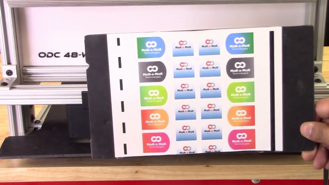
Roll-2-Roll Technologies has released a new feature for it's web position sensors. This feature benefits all converting operations. The advanced contrasting capabilities can detect the smallest changes in colors and markings. Stay tuned for more information about our advanced contrast sensor capabilities for converting operations.
Transcript
Show full transcript (2108 words)
hi this is pivotal Velasco of roll-to-roll technologies today we're going to talk a little bit about our contrast sensing technology in how it works with our web guides you should typically some of our customers come to us a very very special situation they might say for example oh I want to guide this material but they really don't know how how to how can we get something that has gradients that you know that has no line in it well we have found a method of doing that we can guide based on it labels on the edges of labels we can guide based on features or contrast between colors and we'll talk a little bit about that we can even guide on labels that have irregular features as long as we can find something that we can guide through so today we're going to talk a little bit about what each one of these features how to go through our menu of applications for contrast sensing in web guiding applications so when you go to the screen you will see that there's a tool icon right there let's press on that tool icon that tool icon was tickets to another screen where you can see that we're on the sense sensing mode right let's hit the tool icon on top again and then we get the different this is the the screen where you will get all the different options for doing the contrast sensing in this case when it's red it means that it's already set on a specific application so now what we're gonna do is let's see all the different applications you can do by hitting on that icon there it will turn green and it'll show all the different applications now right now it's showing what we consider to be the most robust application that is it's actually seeing the border of both borders of a specific contrast in this case it can be a single color but it's actually working on two principles one it's the color and the second is the width that of that line or that color so as long as it sees that it will continue to guide or follow that based on that that is the most robust application we have for contrast sensing however the next most robust applications are actually the two on the end in this case when we hit it there it just means that it's going to look in a contrast on on a color that it's represented right now but this orange bar but it's looking and where that contrast begins from this side right and on the other side does the opposite right so in a second we'll see all these applications in working right and the least robust but it's still very useful is this one where it actually looks at to contrast and and then it looks at where those two countries are actually occurred okay so once we select that we can actually go with these two icons on top we can actually select which one of those in a specific contrast setting we can which one we will select and we'll show that in a little while when we do our applications so if I want to just set I just hit this icon again and now it's on the on this application which is looking at the other line that is caused by two different contrasts in there right and then I just hit back on the home button and takes me back to the original screen so I'm not going to show you different applications with some materials that I have here so for example we can have an application where we have labels printed on a material but you can see the labels only have this permanent edge and on this side it has an irregular feature so one application that we can do is we can actually tell the the system to look for this edge right here now this is one of the most interesting features of our sensors even though these are different colors and ingredients we can still guide on this line right here and even though there's a break in between there's a special condition in our in our in our system where what it will do is if it's in a guiding mode as soon as it sees this this break it will actually lock the position of the web guide at that and then once it sees it the the contrast again then it will go back to guiding mode so of course if this is moving really fast it actually you can't really see when the web guide stops when the locks in place because it just keeps on okay that's one application another application we'll talk about it's this one see in this case we have something similar but but we can actually we have several options to guide from we can actually guide with this in the middle and we can use the most robust application which is actually saying this is a bar right down the middle even though you see that there's a gradient there because of a way our sensors and controls are made that technology that we have it actually looks at this as if this was a line of a constant width so we'll see that application there and of course when we're talking about the lines just the least robust but it has a very good application in the case like this where you have orange and black so we might want to guide on this transition between orange and black okay and we will look at that in a second as we do each one of these applications so let's work with this application in particular so in this case we have an irregular feature on one side but we do have a feature that is constant it's just that there's there's a constant line that we can we can call it a line and the width between here is also constant but we can guide on this feature right here right now which is the edge of all these labels right remember what I mentioned before if there's a break the web guide would lock in position until it sees that material gate and it doesn't care really if the cont if the color changes all it's looking for is this edge right here so if I position the material right here on our on our sensor one thing that we'll do is first let's go back in the in the in the system and let's go into the tool mode and go all the way back I have already pre-selected but let's say that we were here we can actually do and select this one right here which is the one that we like it's looking from this side to this to the edge right and then I can tell it here by moving right now it's actually looking at the black surface up to the edge where it starts with white but I don't want a guy there I want a guide on the white on this edge right here so I can move it the position right there and I can tell it lock it there and now it is locked and then I go back in my home program and as you can see you see this is the black material on the back this is the black material on the back this one here is this white up to the edge of the label and this is the label but as I move it let's put it right here and say it's in the center and as I move it you'll see that once it loses the contrast it will lock in position you see it keeps it all the way through I mean and that's what I'm looking for and you'll see a green line which actually tells you in this case it's actually looking at the place where this white between the labels and it has locked in position there so no matter what I do as long as I keep it there you see that the green the green line stays but as soon as I move it it picks it back up again now let's look at this application in this case we see that the best way of guiding with this material would be looking at what is constant the only constant we have here that we're sure of is that the width between this this a feature here or this label and in the other label so it creates kind of like we're gonna call it like a white line even though it's has gradients right however the width is constant throughout so we're gonna work on that one place the material right here and then we're gonna go into our menu and then we're gonna select the appropriate feature that we want so we're gonna do the one in the middle remember I told you one before that it is the most robust feature there is however I do have to pick which one I'm looking at I know it's this one and right in the middle which is the white space between the two labels so I can select it right there and then I say let's pick that and it is set when I go back to my main menu as you can see the green says that is right in the middle and as I move it around you see how it follows the material based on that but notice that when it loses it it locks in position until it finds it again that is one of the main features of our system now in this case we want to do something very interesting we might have a feature which is kind of hard to detect in this case we have orange and black we want a guy by the line that is created between that transition from orange and black so what we do is we go back in our menu right and then we pick which one we want and we're going to pick this one right here now here's something very interesting once we I have picked it I can also say I can have to I have to select it right through here so what I know is right now the transition this bar right here is the orange this is the black this is the white and I can move it around I can say pick on this one or pick on that one ring but I want to do this one which is a transition as you'll see you'll see a green light or a green line that goes around the two features right and it's going to be right in the middle there where the transition occurs because I picked that one which is right in the middle here I can go back in my menu and you can see right there where the Green Line is right where the black and orange meet right now what is a special that this feature is that it will only look at where orange and black comes in that arrangement Orange on this side black on that side you know we'll just follow that feature through me and if it loses it like before it just locks in the last position but then when it's picked it back up he keeps alone now I have another orange in black but if I put that one there see it's not gonna pick it up it's not on the right orientation right so that is one of the features another feature that we have with this so we hope that this information is of value to you we know it should be we're really interested in knowing any other applications you might think of however think of this we have a web guiding technology that uses contrast sensing that can handle very difficult applications where where the contrast has really has some some very specific features such as gradients maybe irregular features as long as we can find something where we can guy from we can provide you a good guiding system based on contrast you can see more of this in other features that we have in our in our products by visiting our website which is WWF tag team thank you you
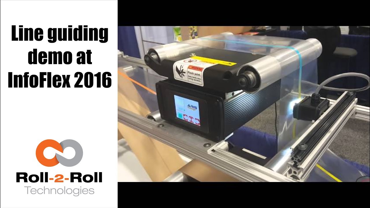
The line guiding capabilities of the compact web guiding system is enabled by the ARIS web position sensor as shown in this demo video.
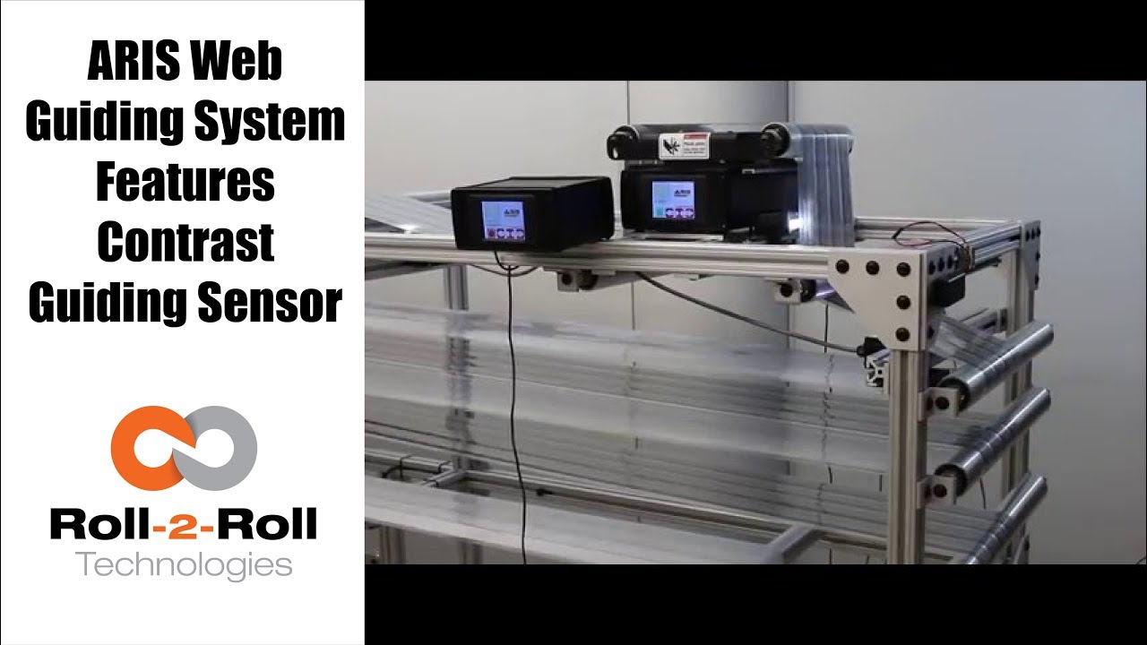
Roll-2-Roll Technologies compact web guiding system can be used for contrast guiding with the ARIS Web Position Sensor as shown in this video.
Transcript
Show full transcript (297 words)
our web guiding system ARIS features the latest in web guiding technology it adapts to any material, requires no calibration and is very simple to setup. Now it features a comprehensive guiding sensor that can be used in any kind of sensing including edge, line, contrast, composite or layered web detection. In this video we use two web guides as a test machine to introduce several speeds and disturbance frequencies. One web guide creates a disturbance while the other correct this disturbance.
This test allows us to evaluate how our machine adjust to these different disturbances. This video shows contrast guiding of composite web where the web is guided based on a die cut of the label. Our web guides can work with continuous or intermittent lines or contrasted edge. Our edge sensor detects the web position of any materials used without the need for manual adjustments.
A previous version of our sensor used a reflection of infrared light to take a picture of the edge of the material. These pictures and processed using digital signal processing algorithms to accurately sense the true position of the material irrespective of its physical properties. The updated version is more comprehensive and uses white light to take a picture of the web materials and in the line detection mode, the sensor can handle a solid or intermittent line or even in contrast between two materials. As you can see this video, the web guide is unaffected by missing labels.
Our tests have shown our sensor technology works automatically with materials of varying contrast. The use of fiber-optic technology eliminates a need for focusing and eliminates need for calibration and set-up. There are details on these experiments available in our white papers. You can find a link in our description below.

Check out the many capabilities our sensors have in edge, center, width, contrast and mark sensing. Our sensors require no calibration. These advanced sensor capabilities are shown here in this video.
Transcript
Show full transcript (756 words)
This Pedro Velasco with Roll-2-Roll Technologies And we want to show you a little bit more about our sensor technology and its different applications. So here we have a demo set up to show some of the features that are sensors have. Right now we're showcasing the 221 infrared sensor and on the left side you'll see the forty eight millimeter white light sensor which we used mostly for contrast sensing so we have already set up the Infrared sensor and we're going to do first let me show you the in the edge mode all the capabilities that it can do. So they can do so right now number one.
It can actually tell you exactly where the sensor is mounted and Which side is that it's that said its absolute sensing so as you can see it automatically detects a sensor And then it's affecting the edge on this side, right? but I Want [to] change it. Just press here if I come from this side? See it automatically detects no calibration needed for this operation.
Additionally we have other characteristics that we can do with this we can do something with this same sensor. We can measure width. We set it up to monitor in this case. It can be a pass or fail condition so now there's no material, so I'm gonna put a material here, and then I'm going to set a Condition and I'm going to set it up.
Let's say I want to accept two millimeters off That's accept so now it has recorded the distance that just width that I want right? but put another material, that's a different width It will leave me a fail condition because it's beyond the limits that I've all already set up over here So that's another characteristics of our sensors. We can also show you another which is the string mode right here for the 221 sensor if I present one string? will actually see one string.
But that is the same time you can also see two strings and you can see even Three and many more right, but the best thing that we can do is we can actually also give you the distance between the strings between the edge of the strings, so in this case is telling us between the third and First string there's Thirty six millimeters right however we can adjust this, prepare you with our system so that they can actually tell you the difference between individual strings Now let me hook up now our White light sensor so as you can see I'm just going to unhook our 221 sensor infarred sensor And then I'm going to just hook up The light light sensor as you can see it turns on immediately It detects it and of course a white light sensor can do edge guiding. All right Just this the other sensors You can do it from either side, it auto detects. But I can also select the mode So right now. It's going to do contrast sensing So it will tell me The position this contrast as you can see by that?
Green and Red bar right, but I can also tell you Not only that I can tell you the width of that So it gives us a 9-millimeter width, if I change it and see, it changes. of course, if I Had a steady hand this little better, [okay]? [okay], so that's one of us the many features that we have and that's with the white light sensor the contrast capabilities also, we [can] also give you a Mark so let's say for example. You have something like [this] We wanted to detect the mark, so as soon as the sensor sees it It will tell me that the mark is detective.
Mark detected. This comes across, so this has multiple applications if you had For example. We can actually give you the distance between marks through a one of our algorithms But the best thing we can do is, we can also do this with ultraviolet light and then you can have a mark with UV ink which can also be detected. So these are some of our capabilities that are sensors can do.
Of course now we're looking for other applications As we do our research in our developing products by right now these are available to you. Just give us a call or visit our website, and you can actually see your products there. Thank you very much