
March 28, 2025
In this video, we explore the two main reasons for using center guiding in web handling systems, focusing on the advantages it brings when dealing with varying web widths and poor edge quality. The SCU6x Controller's advanced sensor technology allows seamless adjustments without the need to move sensors, accommodating significant width changes efficiently. This ensures high response times and minimizes wear on actuators.
Transcript
Show full transcript (529 words)
there are two main reasons why somebody would use Center guiding one is if you're changing web widths and you want to align the material to the center of the machine then Center guiding is the best option where you would place two sensors on either side and this those Those sensors are equidistance from the center line of the machine so when the web width changes you don't ever have to move the sensors and it automatically adust adjust itself because it's going to look at the left portion of the web seen by the left sensor and the right portion seen by the right sensor this is one of the common features that we have or common value proposition from our products is that our sensors can go anywhere from 48 mm up to 960 mm that means you can have a WID change of about 996 mm up to about 1920 mm without needing to move move the sensor this provides a lot of range and flexibility to be able to have a system that can adapt to Wick changes on the flight the older generation systems might have some actuators that move the sensors based on the wick change and more often than not what happens is that those actuators have their own control Loop that needs to be tuned the actuators can wear these are the actuators for the sensors that could wear over time and that creates an issue and then the response time especially when you do a WID change on the fly with those kind of systems is going to be much lower than compared to a system with a sensor that is wide enough to cover all the WID changes so that's one of the main reasons for using Center guiding is that you can do different widths without moving the sensors whenever the WID changes the second main reason why you would use Center guiding is that let's say say you have an edge especially some kind of an extruded Edge and the edge quality might not be great so before it goes into a slitter you you have an edge and the edge is not that great instead of aligning to one edge of the web in that case if you use two sensors and then use the center line position it takes the average of the left Edge and the right Edge and does the measurement that is going to be the center line measurement and it's going to guide the web to the center this is one of the biggest Advantage for using two sensors in doing this inter guiding and especially when you have irregular edges those edges variations are not going to be identical on both sides this Smooths out your edge profile and allows you to guide the web in the middle of the machine and that significantly improves the wound roll quality especially if you don't have a pretty good slit Edge so the advantage is that you are averaging based on two Edge measurements and this helps in smoothing out the edge position those are the two main reasons why you would use Center guide
Different terms related to web guiding are discussed in this article.
Web Guiding
Web guiding is the process of regulating the cross machine position of the web while the web is transported over the rollers in roll-to-roll processing machinery. Other terms for web guiding include:

February 3, 2018
Web width measurement with ARIS web position sensor from Roll-2-Roll Technologies is shown in this video. The capabilities of the sensor include both web width measurement and monitoring.
Transcript
Show full transcript (293 words)
Roll-2-Roll Technologies adds width measurement to its ARIS line of products. Absolute or relative web width can be measured based on the sensor configuration. With two output options the user has the flexibility to monitor the width based on their need. The real-time measurement can be output as an analog voltage between 0 to 10 Volts.
As the width changes the analog output increases or decreases proportionally. In this video absolute web width is measured using ARIS WPS 221 a 221 mm wide sensor. A 7 volt output corresponds to 70% width coverage which is equal to approximately 6 inches. The analog width measurement option can be used for quality monitoring and real-time control of web width in extrusion processes.
For low modulus webs, the width measurement can also be used to monitor necking in the web. The digital output option allows the user to set pass/fail conditions based on web width. A low and a high limit for width tolerance can be set. The resolution of the tolerance is in millimeters.
If the actual measurement is within the negative and positive width tolerance the voltage will be zero; this corresponds to a pass condition. If the width goes below the lower limit the output will be a negative voltage. A non-zero voltage is a fail condition. Similarly if the with goes above the upper limit the output is a positive voltage.
This pass/fail condition can be used for a variety of quality control purposes. For wider webs two sensors can be used for relative width monitoring. In that case the analog output corresponds to the percentage of web covering the two sensors. The absolute width of the web can be obtained based on the physical distance between the two sensors.
For more information please contact us.

February 3, 2018
Roll-2-Roll Technologies is releasing a new bigger and better sensor. Check out this video to learn more and reserve yours today!
Transcript
Show full transcript (264 words)
Hello, this is Pedro with Roll-2-Roll technologies and we're going to talk to you a little bit of our sensors especially the array on sensors that we have available to the market now we have talked before about the WPS 48 which is a 48-millimeter sensing window and the 221 with a wider window available for a mostly center guiding and it can do edge detection as the other can and also it does you know thread counting and it can be used to monitor web width as one of the many features it has. however we're introducing to the market something we just developed in which will be available in May to the industry which is the WPS 440 IR. It includes also the same infrared signal and it has a four hundred forty millimeter sensing window but one of the best features of it all is it even though these require a sensor control unit this has a central control unit enclosed within the same package. All you have to do is connect two cables and the sensor is ready to go.
Now with this you can monitor remotely a web but the same time you can also control a web guiding system. So this is available to the market in May, we're going to be showcasing this at ICE USA 2017. We'll be at Booth 1034 and we can actually see the sensor in operation over there. So in order to get some more information about our products, visit our website the www.r2r-tech.com and see some more about our products thank you
February 3, 2018
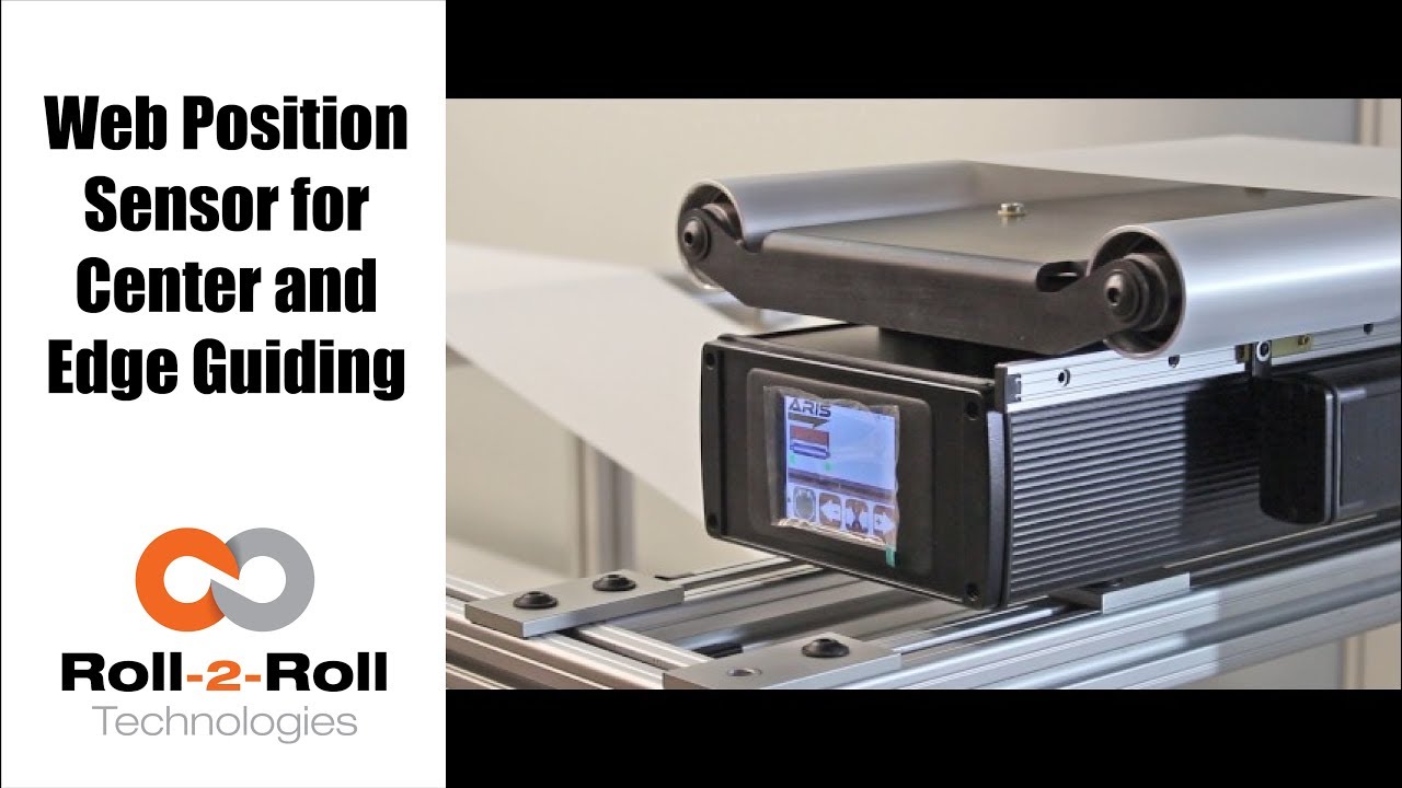
One of the many features of our wide width sensors is the ability to function as a sensor for both edge and center guiding without the need for calibration. See how easy it is to use one sensor for both center and edge web guiding applications in this demonstration of switching from edge guiding to center guiding on-the-fly.
Transcript
Show full transcript (196 words)
Today we want to show you another of the features of our sensors In this case, we have a 221 mm sensor, we can use for center guiding and at the same time for edge guiding, you just by flipping on off switch. Right now We have it set on a 15 inch guide. And it right now set up and run, as a center guide. However so what I'm going to do now we don't recommend you do it on your machine but just to show you how easy it is to just switch the one from center guiding to edge guiding.
So right now as you can see its set on center guiding. Now, I'm going to put the web guide out of automatic to manual and then I'm going to slide the sensor all the way for the position where it's going to be edge guiding on the same position that we have it right and then I'm going to turn it back on and and do edge and find sensor, and I'm going to turn it back on. You can see the maintain same position It's doing exactly edge guiding in the same position.

February 3, 2018
Check out the many capabilities our sensors have in edge, center, width, contrast and mark sensing. Our sensors require no calibration. These advanced sensor capabilities are shown here in this video.
Transcript
Show full transcript (756 words)
This Pedro Velasco with Roll-2-Roll Technologies And we want to show you a little bit more about our sensor technology and its different applications. So here we have a demo set up to show some of the features that are sensors have. Right now we're showcasing the 221 infrared sensor and on the left side you'll see the forty eight millimeter white light sensor which we used mostly for contrast sensing so we have already set up the Infrared sensor and we're going to do first let me show you the in the edge mode all the capabilities that it can do. So they can do so right now number one.
It can actually tell you exactly where the sensor is mounted and Which side is that it's that said its absolute sensing so as you can see it automatically detects a sensor And then it's affecting the edge on this side, right? but I Want [to] change it. Just press here if I come from this side? See it automatically detects no calibration needed for this operation.
Additionally we have other characteristics that we can do with this we can do something with this same sensor. We can measure width. We set it up to monitor in this case. It can be a pass or fail condition so now there's no material, so I'm gonna put a material here, and then I'm going to set a Condition and I'm going to set it up.
Let's say I want to accept two millimeters off That's accept so now it has recorded the distance that just width that I want right? but put another material, that's a different width It will leave me a fail condition because it's beyond the limits that I've all already set up over here So that's another characteristics of our sensors. We can also show you another which is the string mode right here for the 221 sensor if I present one string? will actually see one string.
But that is the same time you can also see two strings and you can see even Three and many more right, but the best thing that we can do is we can actually also give you the distance between the strings between the edge of the strings, so in this case is telling us between the third and First string there's Thirty six millimeters right however we can adjust this, prepare you with our system so that they can actually tell you the difference between individual strings Now let me hook up now our White light sensor so as you can see I'm just going to unhook our 221 sensor infarred sensor And then I'm going to just hook up The light light sensor as you can see it turns on immediately It detects it and of course a white light sensor can do edge guiding. All right Just this the other sensors You can do it from either side, it auto detects. But I can also select the mode So right now. It's going to do contrast sensing So it will tell me The position this contrast as you can see by that?
Green and Red bar right, but I can also tell you Not only that I can tell you the width of that So it gives us a 9-millimeter width, if I change it and see, it changes. of course, if I Had a steady hand this little better, [okay]? [okay], so that's one of us the many features that we have and that's with the white light sensor the contrast capabilities also, we [can] also give you a Mark so let's say for example. You have something like [this] We wanted to detect the mark, so as soon as the sensor sees it It will tell me that the mark is detective.
Mark detected. This comes across, so this has multiple applications if you had For example. We can actually give you the distance between marks through a one of our algorithms But the best thing we can do is, we can also do this with ultraviolet light and then you can have a mark with UV ink which can also be detected. So these are some of our capabilities that are sensors can do.
Of course now we're looking for other applications As we do our research in our developing products by right now these are available to you. Just give us a call or visit our website, and you can actually see your products there. Thank you very much

February 3, 2018
Web width measurement is a common need in the converting industry. This video shows the web width measurement application with the WPS.
Transcript
Show full transcript (275 words)
Hi, this is Pedro Velasco with Roll-2-Roll Technologies. Today we talk a little bit as things that we can do with our sensors. Now our web guides are capable of doing edge guiding or center guiding with just a touch of an icon and that is because of our sensor technology. Now our sensors on their own they can actually have many other features that deal with that application.
For example this 221 mm sensor, we can use it to monitor the width of any material that is within the 221 millimeter sensing window. In this case they can measure the width, it can also detect that there are differences in the width and therefore send out a signal to tell you that there's something wrong with it. Now we can also do that, let's say that the sensing the material is wider than the sensing window. Well we can also use two sensors we can use two 221 mm or 2 48 mm and then hook them up to our sensor control unit and keep on doing that same application which is measuring the web width or at the same time controlling or monitoring the web width in case you want to make sure that the material is within specs in width wise.
This can be done with any of our sensors. This can be done with our 221 millimeter sensor the WPS 221 IR or this can be done with our 48. There are 16 mm sensors too and also with our new sensor the 440. Now this is some of the features that we have and we will talk some more about other features in future videos Thank you very much

February 1, 2018
Do you have an existing web guide with outdated sensors and control unit? We now have a solution with our upgrade kits featuring Roll-2-Roll® Web Sensors and Control Units for all electromechanical web guide systems, providing advanced edge and center guiding capabilities.
Transcript
Show full transcript (2182 words)
Hi, this is Pedro Velasco with roll-to-roll technologies in a previous video we showed you or we talked to you about the advantages of using a retrofit kit when you need to replace your existing web guiding system especially if you're a integrator or a rebuilder of machinery even an end-user. This is one way to save some money, so you keep the mechanical part of your web guide But then you use a retrofit kit in order to improve its application now You're getting the best in controllers and the best in sensors technology available at that time so Whenever you order a kit from us you'll probably get a Control unit which is clearly labeled and helps you in the orientation as to how the screen will be. So you will have the sensor Ports and then you will have on the side power connection the motor connection And if you have order an Ethernet communications option it will be there, too. You will also get a sensor or sensors depending on what your application Maybe even a sensor rail if you need so But that it's up to the user as to where they want to place the sensor.
You also get an actuator With it's a own motor driver and then a servo-center sensor with its brackets right. And then all the other accessories are required in order to do the installation. Ok so the first thing you would like you would want to do when you receive your Your kit is you want to verify that it it's in working condition I mean we do packages the best way possible we want to avoid any problems. So the first thing you do is you power up your control unit and you will receive a Connecting cable like this, but for the sake of this demonstration.
We're just gonna use a pre connected power supply. So you will connected to your power power right and then the screen should light up right and then you can proceed to Connect your sensor now remember our technology allows you to do this without having to do any calibration so it's a very simple and a very simple operation so Here you go, so I have now connected my sensor And I can verify if it's working as you can see on the screen, it's working so that we have done that step so After checking your the control unit with the sensor and just powering it up we want to then proceed to Installing the motor so when you get the motor or the actuator you will get an actuator with the mounting bracket And the motor driver okay? So first of all we just want to do is we're gonna do a wiring here Show you how to how you can connect the wiring, but typically we will give it to you pre-wired now There are some exceptions people have some special requirements And they want to do a wiring themselves, but will also give you instructions how to do the wiring. But in this case we're just gonna go through the whole process so first of all you would have to install the bracket I'm gonna use this The plate that we have for the demonstration purposes, but you would have to have this already pre-drilled It's a 4m 4mm screws and then we just Do the just put the bracket on and screw the bracket on to the plate so one thing that you have to be Cognizant of as we're installing the bracket We also have to install the servo- center bracket.
Now the service center bracket now only has one position it goes to this side right so you have to install it at the same time you're installing the motor bracket and so you use your 4mm 4mm screws and you have to install it within the brackets into the plate So here I show you that I have installed the bracket and installed the other bracket for the motor or for the actuator and the bracket for the servo-center As you can see I have the screws mounted here in here right something you have to consider you have to align the motor make sure that this bracket aligns the motor with the the Connection for the actuator to the web guiding mechanism right and of course the servo- Center. It has a one position only so and that will get installed in the next step. Okay, so once I have all the brackets installed then and I have aligned it then I place the motor and notice that I am placing the motor with the cable side on Opposite of where the several Center bracket is at right. I would screw this on and then I would get the servo Center sensor So in order to install the servo-center when it comes it has two nuts right and so you Put it through the hole on the servo-center bracket install the Locking nut and just Score it back on and one thing that you have to do is we recommend that you have the distance between the face of the servo Center sensor and the screw of the actuator An eighth of an inch is a pretty good distance that will work enough and you can actually adjust that by just adjusting the back Nut in order to create the space Okay, so now that we have installed.
Let me give you a piece of advice because there are certain vibrations on the web guides that is operating and you don't want the servo-center to Sensor to move we recommend that once you have determined the appropriate appropriate distance of the servo-center sensor Just put a little drop of Loctite glue on the back nut and then after you secure the front nut then before you secure it just put a little bit on that too right and that will keep the sensor in position. okay, so now that you have installed the Motor on the motor bracket or the actuator on the motor bracket and the servo- Center on its bracket Then we want to do the wiring. However we provide the driver Motor driver in this enclosure. Now you have two options to put places enclosure within your operation one is a you actually fix it to a plate or something where you can just drill a couple of holes.
We provide the Dimensions for this for you so you can do that that operation. You would probably recommend a m3 and screw on this. However We also provide the option where you can just put it on a din rail, so those are two things you can do when installing. Okay, so When we're going to wire this, it's clearly labeled we will provide you with a sheet where it gives you the locations of each of the wires.
However typically we will send this to you pre wired But in the case that you need to do it on your on your own we have provided this sheet And you'll find that on the p1 section, which is clearly label p1 you will have all the connections for the motor in the Connection from the control unit to the more and on the p5 section. You will have the connections for the servo center unit So before we start connecting cables. Let me give you a word of advice You may not you should not connect the motor Or plug in the connection to the control unit that goes from the motors From the motor driver while the control unit is on This will it's not recommend it so Always every time you can do some operation where you need to disconnect the motor from the motor from the control unit Make sure that the control unit is off Alright, so for the sake of time we went ahead and wire to this. This took us about five minutes to do the wiring but as you can see we followed the table that we have here.
It's all pre-wired according to the table and as I mentioned before never plug the motor driver to the control unit while the control unit is on. So as you can see right now we have we have our control unit off. We're gonna go ahead and proceed and connect the motor driver to it. Now that I've That I've connected the motor driver to the control unit I can proceed to put power to it so Now one thing that we recommend once you do this is just make sure in check that everything is operating so with the control unit on the manual which is when it's lit red.
We can actually check the position of the motor. Just move it around right so We can jog it to one side or jog it to the other side Furthermore we can check the servo-center now. Here's something that we want to tell you about servo- centers sometimes Typically we will send you this already preset But in case it s move or something like that you might notice that the servo- center might be off. It might be because It's in the wrong position, so what you want to do is adjust it.
Now you can find adjust it by moving the servo- center in and out to things you don't want to do you don't want it to be crashing against the the stem of the of the actuator and Second thing is you don't want it to be too far away otherwise it will just go to either one of the Extremes right so once that is set we are ready to then test with the sensor now when we're connecting the sensor to the control unit you have to be very careful because the pins inside the connector are very very fine. So the connector will have a notch and you have to align the notch to the port. So the port rule house will have a notch in there so align those those two and Just don't push it in too hard. Just align them and just screw it right on.
It will come in completely and connect correctly and as you can see right now, so The sensor doesn't detect anything right but right now It's in manual mode, so nothing will happen But I'm gonna check and see and yeah the sensor is actually seeing this the finger in if I put it on automatic Okay it will start moving and then I can verify the sensoring. I servo-ceter again, and it's ready to go when you're specing the motor we actually provide you that the motor comes with an m6 thread On the on the end of the of the shaft motor shaft, however We usually will you know we can work with you if you have another need. Also we can provide you with Different size motors depending on your needs so if you have an application that requires more thrust we can give you a bigger motor or the standard motor that we put in some of our web guides, or if you have a very small application we can use a smaller motor. It's all depends on your needs So all you have to do is just tell us about what your needs are with the motor and you know the connection to this to your web guide it can be you know a Ball joint that you know there's many applications that you can do with this However anytime you need something like this.
We just spec with you we talk to you and we we help you inspecting the The connection for your web guide. So with all the options that we have in motors All the options we have in controls and on it you can apply this to any type of guide Any type of guiding application that you need for example you can use it on a steering guide or a displacement guide even for unwind and rewinds and Just by changing the motor we can use it in any of those applications We we hope this information is useful to you in how to use or how to install one of our retrofit Kits now one thing that we want to emphasize is this is the same technology that is on all our web guides so if you want to see other features that we provide within our control units with our sensors you can look at our some of our other videos that we have through our website. You can see other applications we can do with our sensors. You can see you know how we can actually give you some other features and Make your operation easier to run so We hope this will be a help to you and just contact us or look at our website www.r2r-tech.com